Shield launching counter-force frame and installation and use method thereof

A technology of reaction frame and shield, which is applied in the direction of earth drilling, mining equipment, tunnels, etc., can solve the problems of not being able to fully utilize the performance of the reaction frame, the inability to disperse the reaction force, and increase the work risk, so as to reduce the construction cost. Operational risk, convenient installation and construction, and improved safety

Active Publication Date: 2014-07-30
CHINA RAILWAY 15TH CONSTR BUREAU GRP
View PDF6 Cites 21 Cited by
  • Summary
  • Abstract
  • Description
  • Claims
  • Application Information

AI Technical Summary

Problems solved by technology

[0003] However, if the shield machine needs to start inside the circular tunnel constructed by the mining method, since the formed tunnel is circular, it can only rely on the annulus structure of the formed tunnel to provide support for the shield machine to start excavation. In this way, if the rectangular reaction frame structure is still used, the reaction force provided for the shield machine can only be transmitted through the four corners of the rectangular reaction frame structure, which cannot give full play to the performance of the reaction frame, and the reaction force The transmission of force is too concentrated to disperse the reaction force, which will inevitably greatly increase the technical requirements for the structural surface that provides the reaction force, increasing the risk of work

Method used


Image

  • Shield launching counter-force frame and installation and use method thereof
  • Shield launching counter-force frame and installation and use method thereof
  • Shield launching counter-force frame and installation and use method thereof

Examples


Embodiment Construction

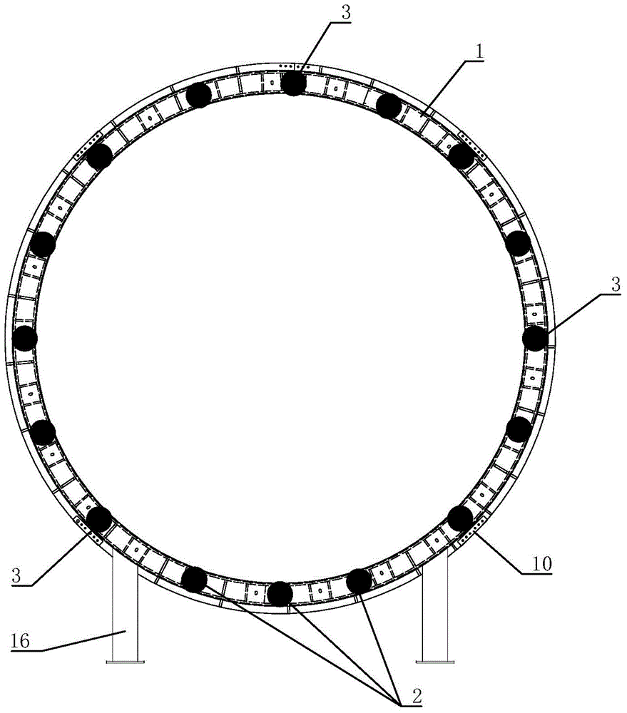
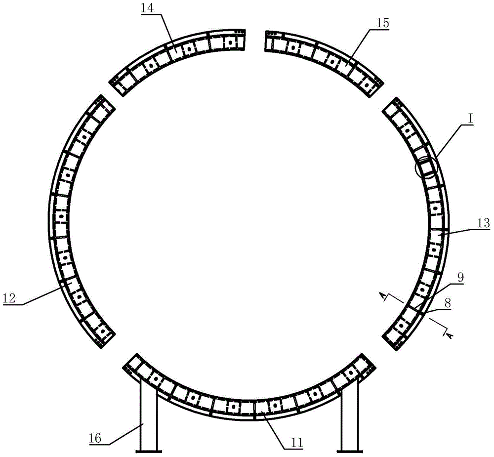
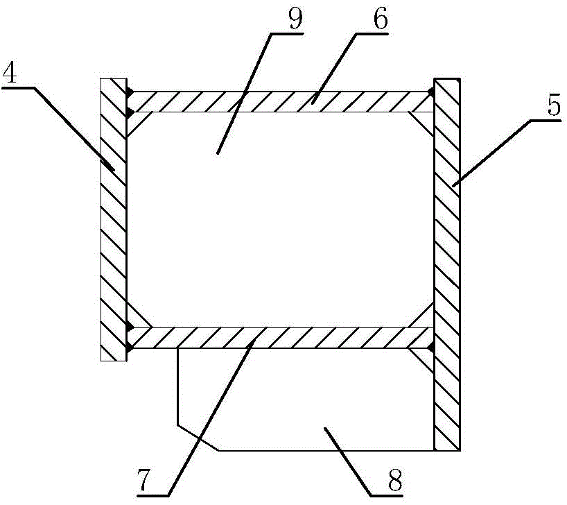
[0025] like figure 1 and Figure 5 and Figure 6 The starting reaction frame of the shield machine shown includes a ring-shaped steel ring body 1 spliced ​​by several arc segments. The front of the steel ring body 1 faces the shield machine, the back faces the secondary lining 17 and faces away from the shield machine. The back of the steel ring body 1 is connected with 16 steel supports along the circumferential direction, including three horizontal supports 2 at the bottom of the steel ring body 1 and an oblique support 3 above the horizontal support 2. The horizontal support 2 is perpendicular to the plane where the steel ring body 1 is located. , the oblique supports 3 are scattered, and each oblique support 3 forms an included angle with the axial direction of the steel ring body 1 . The ring-shaped steel ring body 1 is conducive to providing reaction force for the start of the shield machine in the formed circular tunnel, which can improve the stress environment of th...


PUM


Abstract

The invention relates to a shield launching counter-force frame. Counter-force is supplied for launching of a shield tunneling machine in a formed circular tunnel by means of an annular steel ring body favorably, thus the stress environment of the counter-force frame is improved well, the transmission pathway of the counter-force is transformed, 16 steel supports are arranged on the steel ring body, the steel supports act on the steel ring body simultaneously, the integral strength, stiffness and stability of the counter-force frame are improved, the stress of the counter-force frame is reduced, meanwhile, the steel ring body is formed by splicing multiple arc segments, thus installation and construction of the counter-force frame in the tunnel are facilitated, the risk of construction work is reduced, and the safety of the shield tunneling is increased. The invention also relates to an installation and use method of the shield launching counter-force frame. The shield launching counter-force frame and the installation and use method thereof can be applied to shield construction of the circular tunnel.

Description

technical field [0001] The invention relates to tunnel shield construction, in particular to a shield starting reaction frame and an installation and use method thereof. Background technique [0002] When the shield machine starts to excavate, the forward movement of the shield machine needs to provide reaction force for the excavation of the shield machine through the reaction frame at the back. The reaction frame is generally supported on the reinforced concrete frame at the bottom of the shield starting shaft. Considering the convenience of construction, the shield starting shaft is usually a regular rectangular structure in order to adapt to the support surface that provides the reaction force. [0003] However, if the shield machine needs to start inside the circular tunnel constructed by the mining method, since the formed tunnel is circular, it can only rely on the annulus structure of the formed tunnel to provide support for the shield machine to start excavation. I...

Claims


Application Information

Patent Timeline
Patent Type & Authority Applications(China)
IPC IPC(8): E21D9/06
Inventor 乔水旺王红路吕善李新龙田燕武杨永军
Owner CHINA RAILWAY 15TH CONSTR BUREAU GRP
Why Eureka
Try Eureka