Lever synchronizer

A synchronizer and lever technology, which is applied in the field of auto parts, can solve the problems of bloated structure, the inability to return the gear sleeve 1 normally, and the long axial arrangement of the gearbox.

Active Publication Date: 2014-07-30
WUHU WANLIYANG TRANSMISSION CO LTD
View PDF7 Cites 0 Cited by
  • Summary
  • Abstract
  • Description
  • Claims
  • Application Information

AI Technical Summary

Problems solved by technology

[0004] At present, the boss 5 of the lever unit 4 is mostly a rectangular boss, such as Figure 4 and 5 As shown, the boss 5 of the lever unit 4 is easy to disengage from the gear sleeve 1 after the gear is engaged, that is, the boss 5 of the lever unit 4 is inclined to...

Method used


Image

  • Lever synchronizer
  • Lever synchronizer
  • Lever synchronizer

Examples


Embodiment Construction

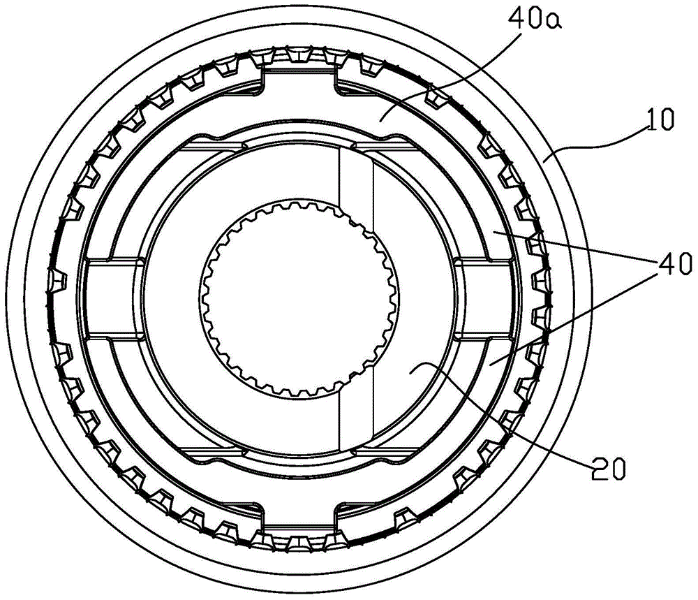
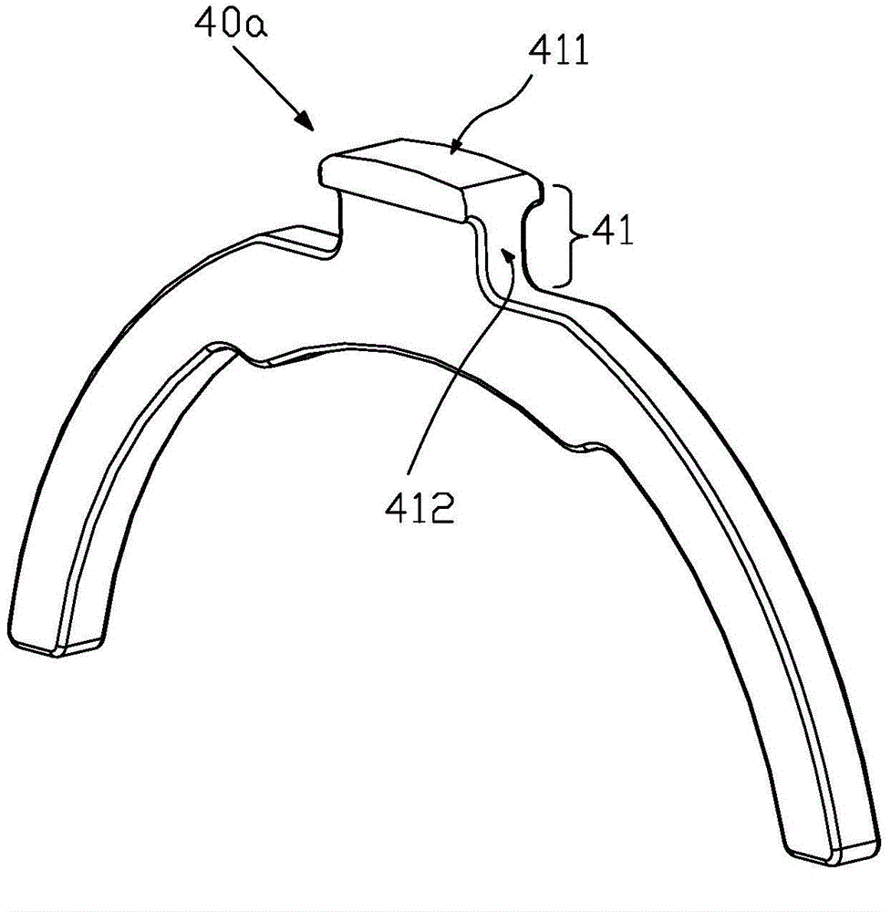
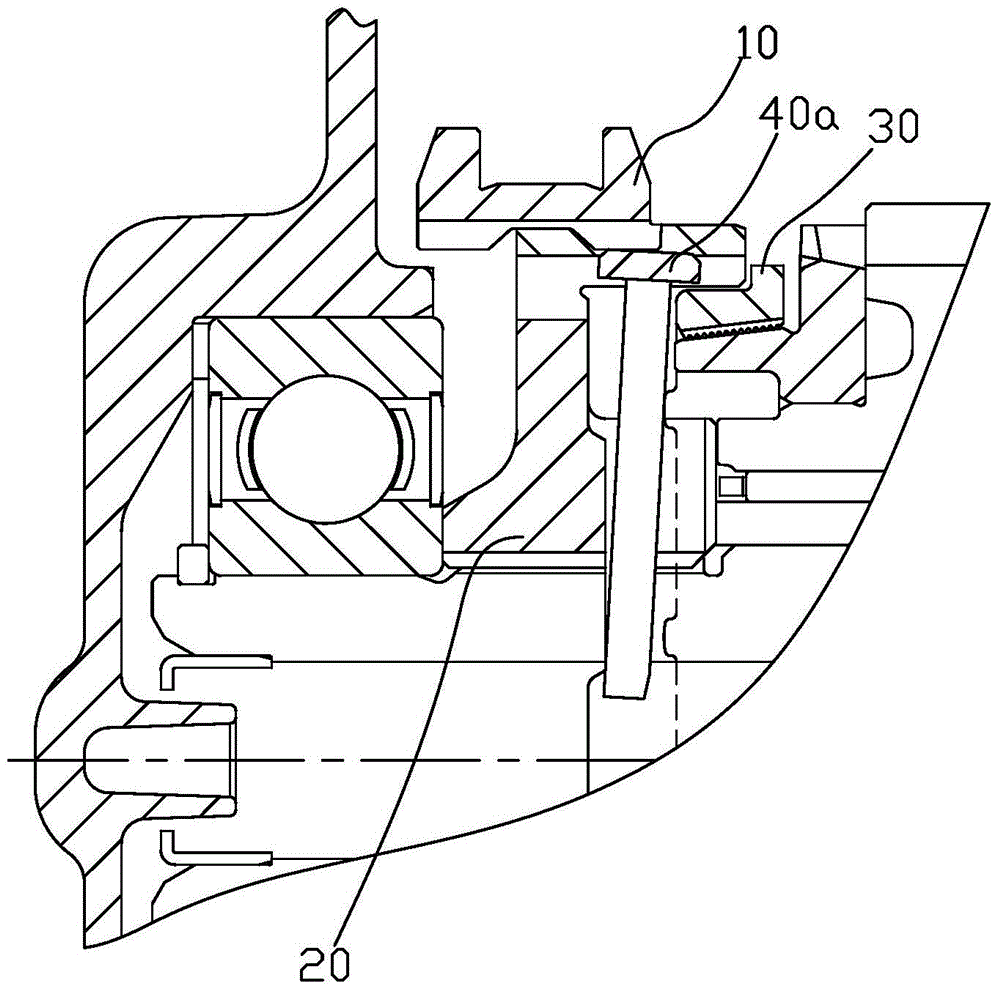
[0013] Such as Figure 1-3 As shown, a lever synchronizer includes a gear sleeve 10, a gear hub 20 and a synchronizing ring 30, a lever 40 is arranged between the gear hub 20 and the synchronizing ring 30, and the described lever 40 consists of two semicircular The lever unit 40a is composed of two semicircular lever units 40a with opposite openings. The arc-shaped top of the lever unit 40a is provided with a boss 41, and the top of the boss 41 is clamped between the gear sleeve 10 and the gear hub 20. Meanwhile, the boss top surface 411 where the boss 41 is in contact with the gear sleeve 10 extends to both sides along the axial direction of the gear sleeve 10 so that the axial section of the boss 41 is T-shaped. The openings of the two lever units 40a are arranged opposite to each other and respectively clamped in the annular grooves on the gear hub 20. The annular grooves of the gear hub 20 provide a fixed point for the lever unit 40a, which is the fulcrum of the lever unit...


PUM


Abstract

The invention relates to the field of automobile parts, in particular to a lever synchronizer. The lever synchronizer comprises a gear sleeve, a gear hub and a synchronizing ring, wherein a lever is arranged between the gear hub and the synchronizing ring; the lever consists of two semicircular lever units; openings of the two semicircular lever units are arranged oppositely; a boss is arranged at the arc-shaped top of each lever unit; the top end of each boss is clamped between the gear sleeve and the gear hub; the boss top surface, contacted with the gear sleeve, of each boss is extended towards the two sides respectively along the axis direction of the gear sleeve so that the axial cross section of the corresponding boss is T-shaped; the boss top surface extended towards the two sides respectively along the axis direction of the gear sleeve can ensure that the gear sleeve and the lever boss are of enough contact surface, so that the boss is effectively prevented from disengaging from the gear sleeve, and normal return of the gear sleeve is ensured. Meanwhile, the width of the gear sleeve is not increased, and the gear sleeve can be designed to be relatively narrow, so that a gearbox becomes compacter.

Description

technical field [0001] The invention relates to the field of auto parts, in particular to a lever synchronizer. Background technique [0002] When a car shifts gears, the power output speed is far greater than the speed of the gear that is about to be shifted into. If you imagine that a slow-rotating gear is forced to mesh with a high-speed rotating gear, tooth grinding will definitely occur. In order to avoid this phenomenon, a synchronizer is required to adjust. The function of the synchronizer is to transfer the energy of the side with a higher speed to the side with a smaller speed through the contact friction of the parts, so that the side with a smaller speed can increase the speed and achieve synchronization with the speed of the side with a higher speed. This can not only ensure normal shifting, but also play a buffer role. It can be seen that the synchronizer is a very important part inside the manual transmission. [0003] The lever synchronizer is a kind of syn...

Claims


Application Information

Patent Timeline
IPC IPC(8): F16D23/02
Inventor 张晓东林健康军波
Owner WUHU WANLIYANG TRANSMISSION CO LTD
Why Eureka
Try Eureka