
Projection lens and projection apparatus

A projection lens and projection device technology, applied in optical components, optics, instruments, etc., can solve the problems of aspherical lens thermal variation, defocus, and affecting the imaging quality of projection lenses, etc., and achieve the effect of eliminating chromatic aberration

Active Publication Date: 2014-07-30
QISDA OPTRONICS (SUZHOU) CO LTD +1
View PDF6 Cites 5 Cited by
  • Summary
  • Abstract
  • Description
  • Claims
  • Application Information

AI Technical Summary

Problems solved by technology

Using a large number of aspheric lenses can easily lead to poor production yield of projection lenses
In addition, as the brightness of the projector increases, the plastic aspheric lens will have defects such as thermal variation and peeling
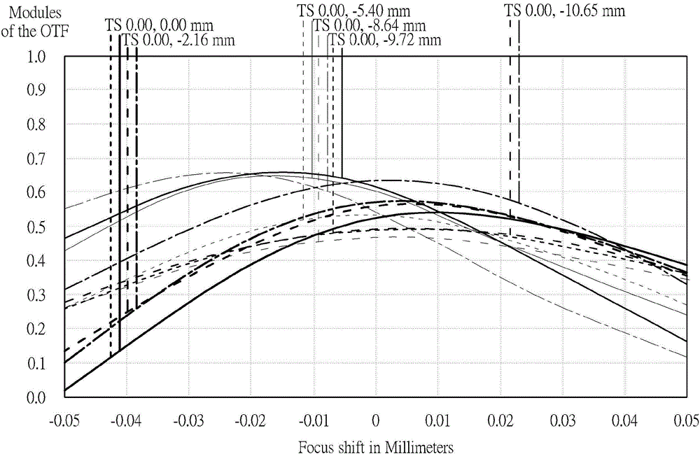
Among them, thermal shift refers to that after the projector has finished focusing, the temperature rises with the time of use, the optical engine (Optical Engine) metal casing produces thermal expansion and the optical components of the projection lens mounted on it produce refractive index changes, resulting in projection Lens defocus (Focus shift / Defocus), which affects the imaging quality of the projection lens

Method used


Image

  • Projection lens and projection apparatus
  • Projection lens and projection apparatus
  • Projection lens and projection apparatus

Examples


Embodiment Construction

[0034] In order to have a further understanding of the purpose, structure, features, and functions of the present invention, the following detailed descriptions are provided in conjunction with the embodiments.

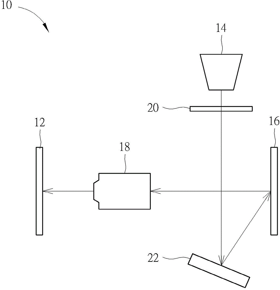
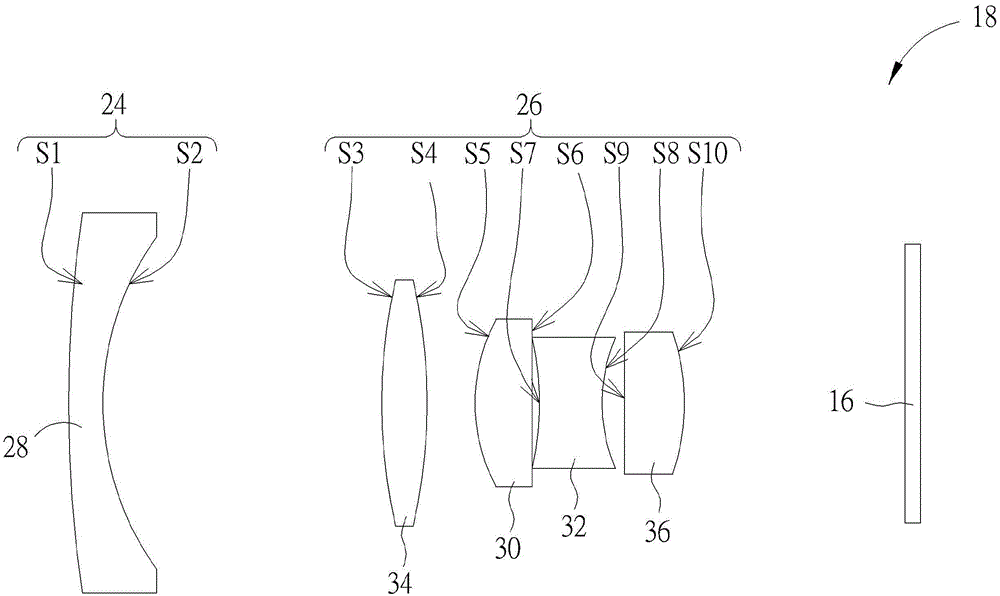
[0035] see figure 1 , figure 1 is a schematic diagram of a projection device 10 according to an embodiment of the present invention. The projection device 10 is used for projecting images onto a screen 12 . The projection device 10 includes a light source 14 , an imaging unit 16 , a projection lens 18 , a filter unit 20 and a reflective element 22 . The light source 14 outputs light, the filter unit 20 receives the light and filters the light into multiple colored lights, and the light processed by the filter unit 20 is reflected by the reflective element 22 and received by the imaging unit 16 . The imaging unit 16 receives multiple colored lights from the reflective element 22 and transmits them to the projection lens 18 . The projection lens 18 is disposed betwe...


PUM


Abstract

The invention provides a projection lens. The projection lens comprises a first lens group and a second lens group, wherein the first lens group is provided with negative diopter, is adjacent to an object side and comprises a first lens with negative diopter; and the second lens group is provided with positive diopter, is adjacent to an image side and comprises a second lens with positive diopter and a third lens with negative diopter; the second lens is disposed between the first lens and the third lens; the third lens is made of a dense flint glass material; the thermal variation parameter of the second lens is D0, and -3.0*e<-5><=D0<=-6.0*e<-7>.

Description

technical field [0001] The invention provides a projection lens and a projection device, especially a projection lens and a projection device that can automatically compensate for focus shift / defocus due to thermal shift. Background technique [0002] In order to save costs, common projectors on the market often use aspherical lenses in the projection lens. Aspheric lenses are usually made of plastic materials. Using a large number of aspheric lenses can easily lead to poor production yield of projection lenses. In addition, as the brightness of the projector increases, the plastic aspheric lens will have defects such as thermal variation and film removal. Among them, thermal shift refers to that after the projector has finished focusing, the temperature rises with the time of use, the optical engine (Optical Engine) metal casing produces thermal expansion and the optical components of the projection lens mounted on it produce refractive index changes, resulting in project...

Claims


Application Information

Patent Timeline
IPC IPC(8): G02B13/00G02B1/00
Inventor 林明坤
Owner QISDA OPTRONICS (SUZHOU) CO LTD
Learn More