
Measurement device and measurement method

A measuring device and spectral measurement technology, which is applied in measuring devices, optical radiation measurement, spectrometry/spectrophotometry/monochromator, etc., can solve problems such as difficulty in determining relaxation time, and achieve high-sensitivity effects

Inactive Publication Date: 2014-07-30
SONY CORP
View PDF5 Cites 19 Cited by
  • Summary
  • Abstract
  • Description
  • Claims
  • Application Information

AI Technical Summary

Problems solved by technology

[0007] However, in the measurement method of the relaxation time using CARS, there is a problem that the determination of the relaxation time becomes difficult due to the influence of the non-resonant background

Method used


Image

  • Measurement device and measurement method
  • Measurement device and measurement method
  • Measurement device and measurement method

Examples


no. 1 approach

[0045] (2-1) About the configuration of the time-resolved stimulated Raman gain measurement device

[0046] (2-2) About the configuration of the time-resolved stimulated Raman loss measurement device

[0047] (3) In the second embodiment

[0048](3-1) About the configuration of the time-resolved stimulated Raman gain measurement device

[0049] (3-2) About the configuration of the time-resolved stimulated Raman loss measurement device

[0050] (4) Variations

[0051] (5) About the hardware configuration of the arithmetic processing device according to the embodiment of the present disclosure

[0052] (6 Conclusion

[0053] (About the technique which is the basis of the measuring device and the measuring method according to the present embodiment)

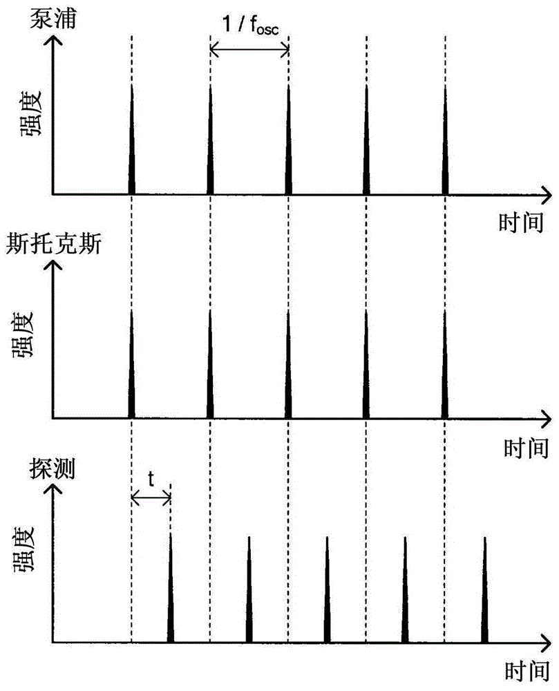
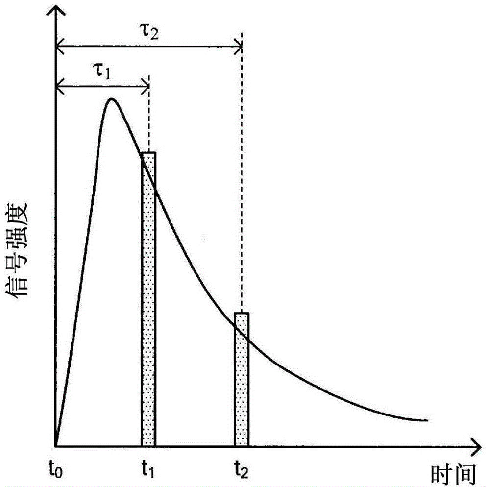
[0054] Hereinafter, before describing the measuring device and the measuring method according to the embodiments of the present disclosure, reference will be made to Figure 1A to Figure 3 A brief description will ...

no. 2 approach

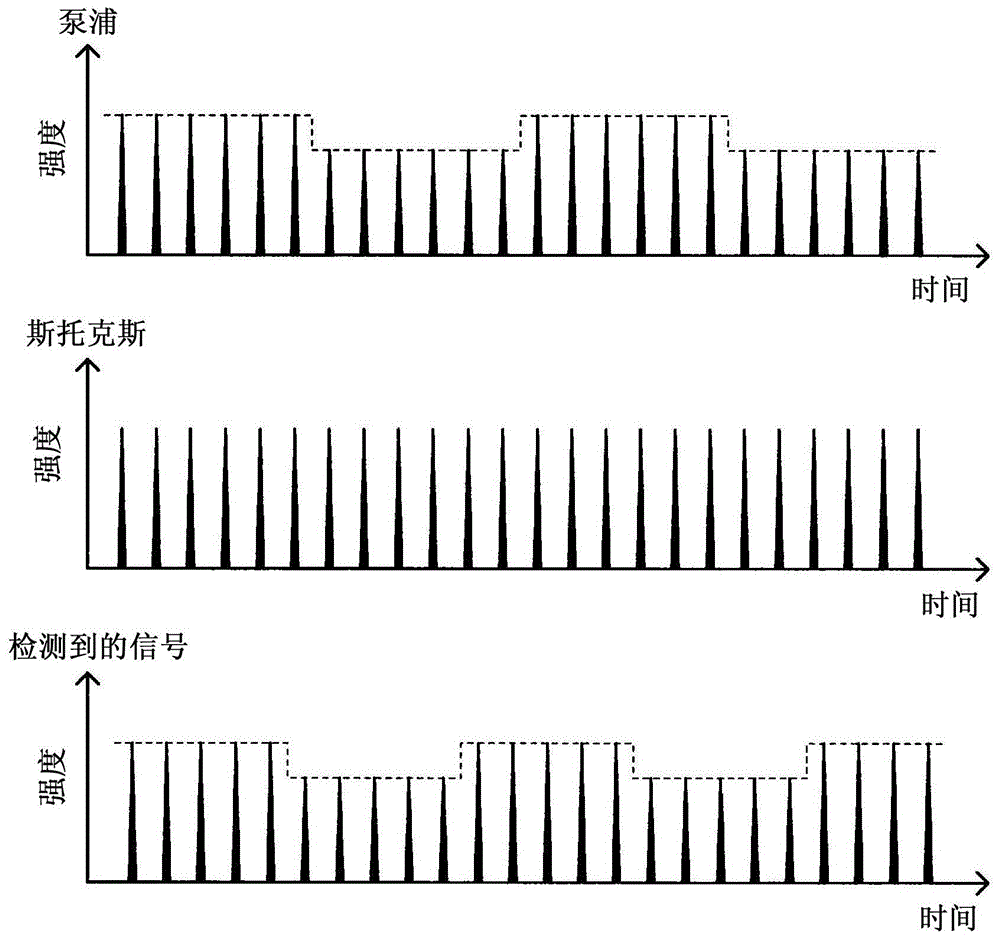
[0188] In the measurement apparatus according to the first embodiment described above, the process of intensity modulation is performed only on the probe light. Here, intensity modulation is performed on Stokes light and pump light by using a second reference frequency different from the first reference frequency used in performing intensity modulation on probe light, and then detection has been made using two different With these two kinds of pulsed light modulated by the reference frequency, the stimulated Raman scattered light was measured simultaneously in both cases in which time delay was performed and not performed. Thus, further accelerated measurement processing can be achieved. Hereinafter, a measurement device according to a second embodiment of the present disclosure in which two kinds of pulsed lights are modulated using two kinds of reference frequencies will be described in detail.

[0189]

[0190] First, refer to Figure 9 to Figure 11 The configuration of...


PUM

PropertyMeasurementUnit
wavelengthaaaaaaaaaa

Abstract

An object of the present invention is to provide a measurement device and measurement method enabling high-sensitivity measurement of the relaxation time of molecular vibration using time-resolved measurement. This measurement device is provided with: a light source unit for emitting a pulsed laser light used for a pump light and a Stokes light for exciting a predetermined molecular vibration in a measurement sample as well as a probe light having the same wavelength as the pump light or the Stokes light, the intensity of the probe light being modulated by a predetermined reference frequency; a pulse control unit for causing a time delay for the probe light generated by the light source unit and thereupon guiding the pump light, the Stokes light, and the time-delayed probe light to the measurement sample; and a detection unit for detecting a transmitted light transmitted through the measurement sample or a reflected light coming from the measurement sample. The relaxation time of the molecular vibration in the measurement sample is measured by time-resolved stimulated Raman gain spectroscopy or time-resolved stimulated Raman loss spectroscopy of the measurement sample.

Description

technical field [0001] The invention relates to a measuring device and a measuring method. Background technique [0002] The vibrational spectral region is very important when considering the application of vibrational spectroscopy, at 300cm -1 to 3600cm -1 The region of the vibrational spectrum in the range is called the molecular fingerprint region. As methods for measuring vibrational spectra corresponding to regions with these wave numbers, infrared spectroscopy and Raman spectroscopy are representative methods, and by using these two measurement methods, complementary information related to the molecular vibrations of a sample can be obtained . Here, in the case of a sample such as a biological sample containing water as a main component, a vibration spectrum caused by water is observed in infrared spectroscopy, and thus Raman spectroscopy is mostly used. [0003] However, in the analysis, inspection, and diagnosis of biological materials, the Raman spectrum of biol...

Claims


Application Information

Patent Timeline
Patent Type & Authority Applications(China)
IPC IPC(8): G01N21/65
CPCG01J3/0208G01J3/0218G01J3/1256G01J3/44G01N21/65G01N2021/653G01N2021/655G01N2201/067
Inventor 玉田作哉
Owner SONY CORP
Learn More