
Spring rubber seismic reduction and isolation system of bridge

A shock-absorbing and isolating rubber technology, which is applied in bridges, bridge parts, bridge construction, etc., can solve the problems of affecting the safety and comfort of driving on bridges, the inability to effectively eliminate earthquakes, and the high cost of shock-absorbing and isolating systems. It is easy to achieve Prefabrication and assembly, easy setup, effect of reducing horizontal shear displacement

Active Publication Date: 2014-08-06
SHANGHAI URBAN CONSTR DESIGN RES INST GRP CO LTD +1
View PDF7 Cites 21 Cited by
  • Summary
  • Abstract
  • Description
  • Claims
  • Application Information

AI Technical Summary

Problems solved by technology

[0003] However, the applicant found that the cost of the existing bridge shock absorption and isolation system is relatively high, and for the ball steel, basin type or PTFE slide bearings used in the existing bridges, there is a large residual displacement under the earthquake. After the earthquake, the residual horizontal displacement caused by the earthquake cannot be effectively eliminated, and the beam body installed above the spherical steel, basin or PTFE bearing will produce horizontal residual displacement, especially the relatively large residual displacement of the transverse bridge, which greatly It will affect the safety and comfort of driving on the bridge, and there is also a potential safety hazard of beam falling. If the existing bridge bearings are replaced with the above-mentioned shock-absorbing and isolating bearings, the cost will be expensive.

Method used


Image

  • Spring rubber seismic reduction and isolation system of bridge
  • Spring rubber seismic reduction and isolation system of bridge
  • Spring rubber seismic reduction and isolation system of bridge

Examples


Embodiment Construction

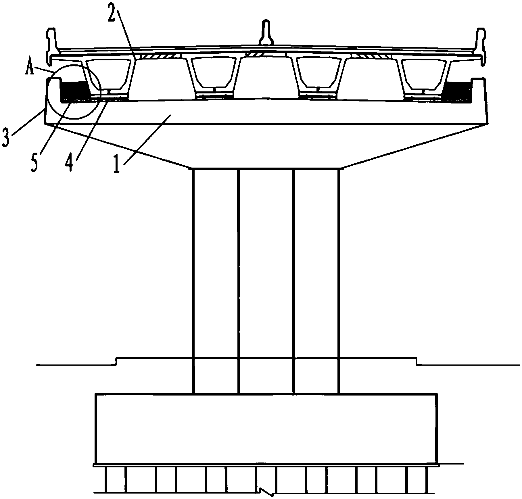
[0020] Such as figure 1 As shown, a spring rubber shock-absorbing and isolation system for a bridge in this embodiment includes a cover beam 1 and a beam body 2. Both ends of the cover beam 1 extend upward to form a stopper 3, and between the two stoppers 3 The top surface of the cover beam 1 is provided with a number of sliding friction bearings 4, the beam body 2 is stacked on the top of the cover beam 1 through the sliding friction bearings 4, and there is a gap between the beam body 2 and the stoppers 3 on both sides .

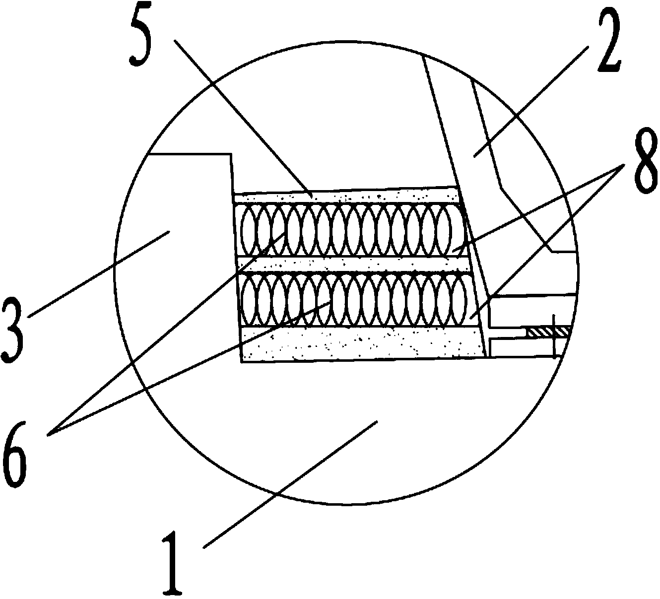
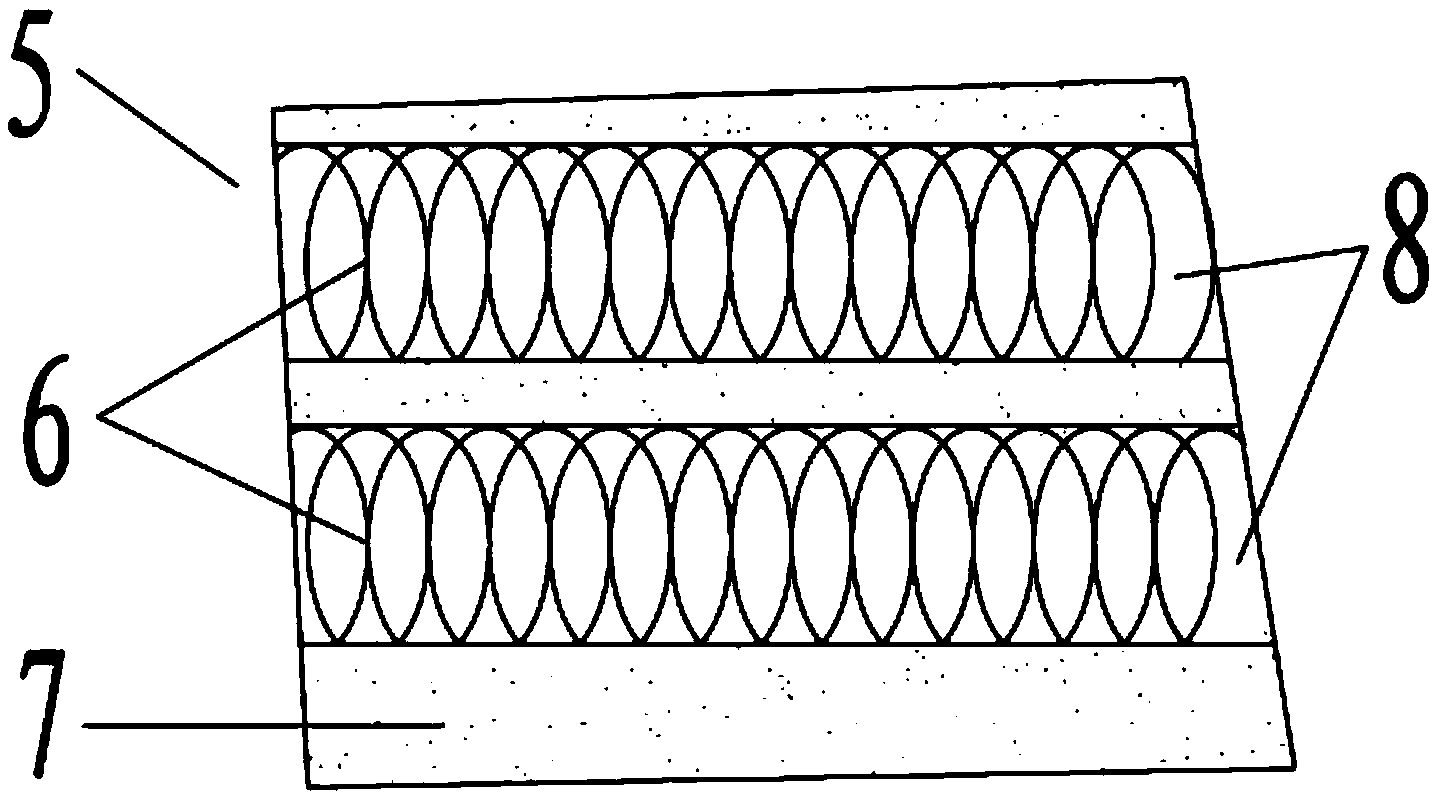
[0021] combine figure 2 As shown, the gap is filled with a spring rubber self-resetting spacer 5, the spring rubber self-resetting spacer 5 is a rubber block 7 with a spring 6 inside, and the two ends of the spring 6 are connected to the beam body 2 and the stopper respectively. on block 3.

[0022] Specifically, such as image 3 As shown, the rubber block 7 is horizontally provided with several through holes 8 for passing through the spring 6 , and a...


PUM


Abstract

The invention discloses a rubber spring seismic reduction and isolation system of a bridge. The rubber spring seismic reduction and isolation system comprises a capping beam and a beam body. The two ends of the capping beam extend upwards to respectively form a stop block, a plurality of sliding friction supporting bases are arranged on the top face of the capping beam between the two stop blocks, the beam body is stacked above the capping beam through the sliding friction supporting bases, gaps are reserved between the beam body and the stop blocks on the two sides, the gaps are filled with spring rubber self-reset cushion blocks, the spring rubber self-reset cushion blocks are rubber blocks with springs arranged inside, and the two ends of each spring are connected to the beam body and the corresponding stop block respectively. The rubber spring seismic reduction and isolation system meets the requirement for seismic reduction and isolation, for horizontal shear displacement in the transverse direction of the bridge generated by an earthquake in the earthquake generation process, the horizontal shear displacement influence of the earthquake on the beam body can be effectively reduced, the rubber spring seismic reduction and isolation system has good self-reset capacity, post-seismic residual displacement is obviously reduced, and safety and comfort degree for driving on the bridge are effectively improved.

Description

technical field [0001] The invention relates to the technical field of shock absorption and isolation of bridges, in particular to a spring rubber shock absorption and isolation system of a bridge. Background technique [0002] my country is an earthquake-prone country located in the affected areas of two strong earthquake-prone regions, the Pacific Rim and the Eurasian Belt. How to adopt appropriate anti-seismic and anti-seismic design strategies to improve the anti-seismic performance of bridges is a problem that must be taken very seriously in bridge design. At present, the vibration isolation system of bridges is mainly to set vibration isolation on the bridge structure, such as lead core rubber isolation bearing, high damping rubber isolation bearing, pendulum type sliding friction bearing or combination of bearing and damper, etc. The shear deformation of the shock-absorbing support itself is used to isolate the upper and lower seismic movements, and the seismic energ...

Claims


Application Information

Patent Timeline
IPC IPC(8): E01D19/00
Inventor 闫兴非王志强周良彭俊汪罗英
Owner SHANGHAI URBAN CONSTR DESIGN RES INST GRP CO LTD
Learn More