Locking device with automatic unlocking function
A locking device and disengagement technology, applied in the direction of fixing devices, mechanical equipment, etc., can solve the problems of inconvenient operation and low work efficiency, and achieve the effect of easy operation, reliable work, and reliable locking.
- Summary
- Abstract
- Description
- Claims
- Application Information
AI Technical Summary
Problems solved by technology
Method used
Image

Examples
Embodiment Construction
[0019] Embodiments of the present invention will be further described below in conjunction with the accompanying drawings.
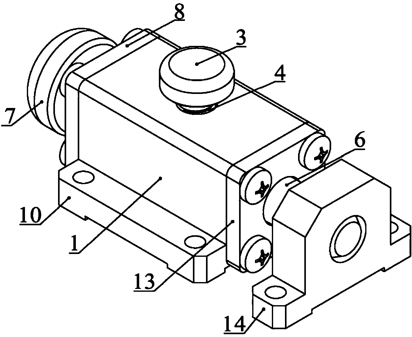
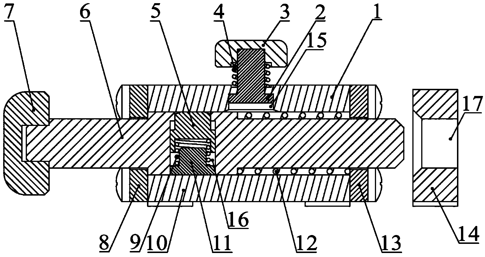
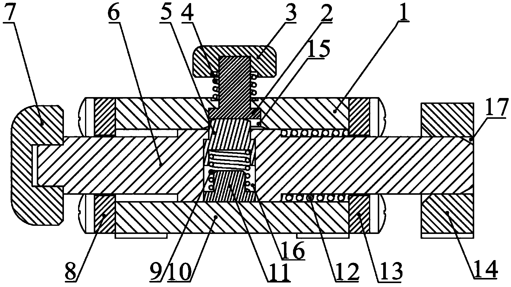
[0020] See attached figure 1 , attached figure 2 , attached image 3 And attached Figure 4 , a locking device that can be automatically disengaged in the present invention includes a guide seat 1, a support base plate 10, a telescopic rod 6 and a positioning hole seat 14;
[0021] The lower end of the guide seat 1 is fixedly connected with the support substrate 10, and a square guide cavity is formed in the middle, and a limiting hole 15 is opened above the guide seat 1, and a release mechanism is arranged in the limiting hole 15;
[0022] The telescopic rod 6 is located in the square guide cavity, and can freely expand and contract therein. The middle section of the telescopic rod 6 is square, and the cross-sections at both ends are circular. The side length of the square is longer than the diameter of the circle. There is a cylindrical guide hole...
PUM
 Abstract
Description
Claims
Application Information
 - R&D
- Intellectual Property
- Life Sciences
- Materials
- Tech Scout
- Unparalleled Data Quality
- Higher Quality Content
- 60% Fewer Hallucinations
Browse by: Latest US Patents, China's latest patents, Technical Efficacy Thesaurus, Application Domain, Technology Topic, Popular Technical Reports.
© 2025 PatSnap. All rights reserved.Legal|Privacy policy|Modern Slavery Act Transparency Statement|Sitemap|About US| Contact US: help@patsnap.com