Color mixer and reversing valve device thereof

A reversing valve and valve body technology, which is applied to valve devices, cocks including cut-off devices, mixers, etc., can solve the problem that the accuracy of a small amount of color paste cannot be guaranteed, the efficiency of a large amount of color paste is affected, and a small amount of color can not be achieved. The problem of paste injection, etc., can reduce the phenomenon of color paste drying, the structure is simple, and the effect of preventing color paste drying

Active Publication Date: 2014-08-06
ZHENGZHOU SANHUA TECH & IND
View PDF8 Cites 53 Cited by
  • Summary
  • Abstract
  • Description
  • Claims
  • Application Information

AI Technical Summary

Problems solved by technology

However, due to the influence of the surface tension of the fluid, when a small amount of color paste is required for color matching, the color paste is often hung at the paste outlet with a larger cross-sectional area, and it is impossible to inject a small amount of color paste
That is to say, the slurry outlet with a large cross-sectional area cannot guarantee the injection accuracy of a small amount of color paste
Obviously, a small cross-sectional area of ​​the slurry outlet can effectively improve the accuracy of injecting a small amount of color paste, but it will directly affect the injection efficiency of a large amount of color paste, and a small cross-sectional area is more likely to cause clogging

Method used


Image

  • Color mixer and reversing valve device thereof
  • Color mixer and reversing valve device thereof
  • Color mixer and reversing valve device thereof

Examples


Embodiment 1

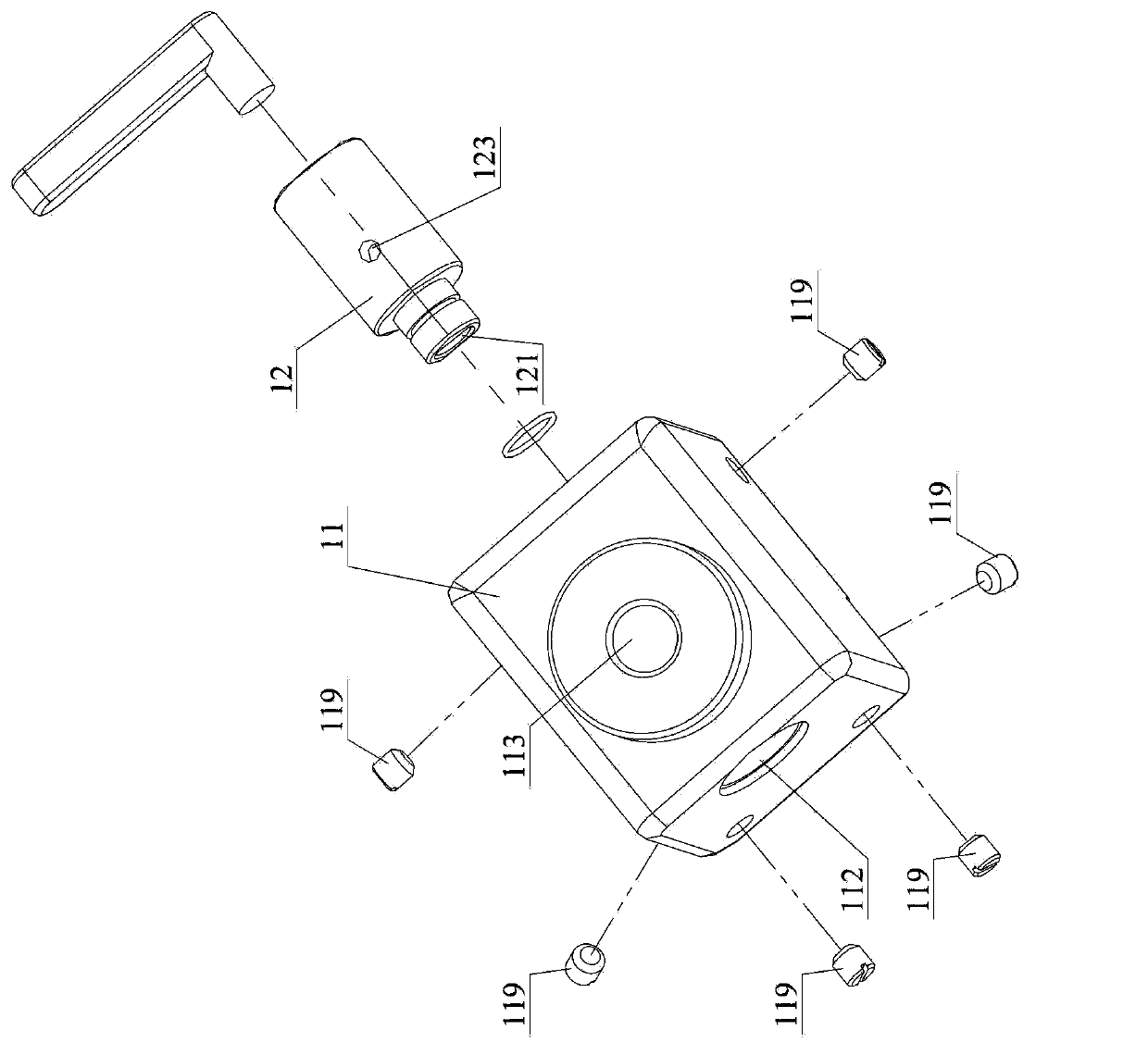
[0073] See image 3 , Figure 4 with Figure 5 ,in, image 3 It is an exploded schematic diagram of assembly of the reversing valve device described in the first embodiment, Figure 4 It is a top view of the reversing valve device described in the first embodiment, Figure 5 It is the front view of the reversing valve device described in the first embodiment.

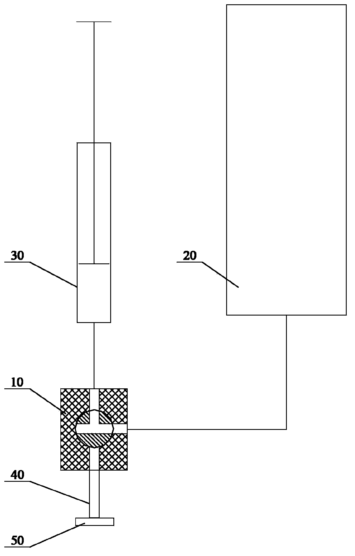
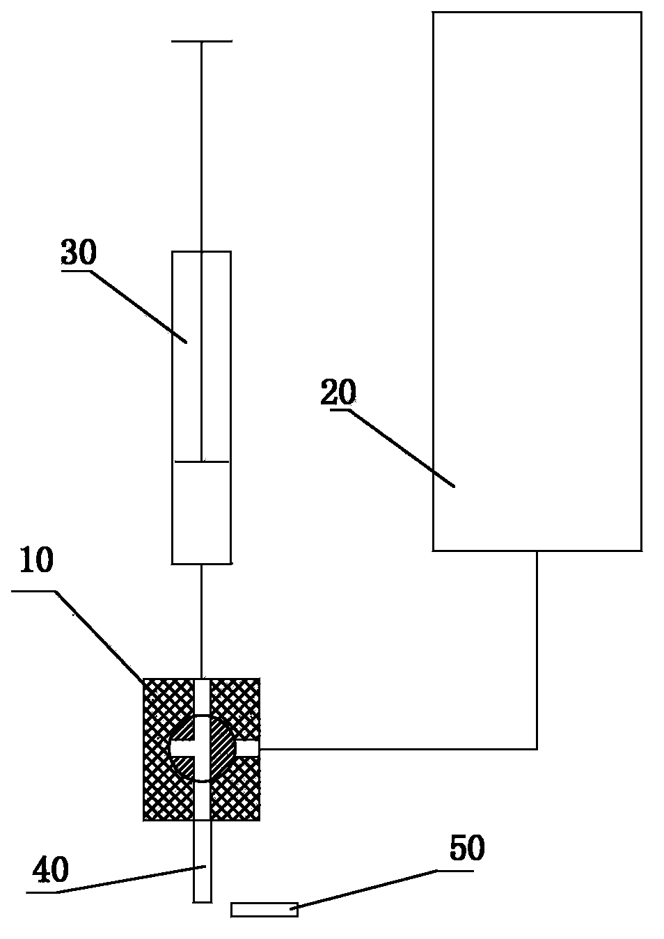
[0074] In this embodiment, the main functional parts constituting the reversing valve device include a valve body 11 and a valve core 12, wherein the valve body 11 has an internal valve cavity 111 for accommodating the valve core 12, and the valve core 12 is pivotally connected to the internal valve cavity , so that it can be rotated to switch to different working positions and establish different conduction relationships. The valve body 11 is also provided with a first opening 112 and a second opening 113 communicating with the internal valve cavity 31. The first opening 112 is used to communicate with the color p...

Embodiment 2

[0085] See Figure 12 , Figure 13 , Figure 14 with Figure 15 ,in, Figure 12 It is an axonometric schematic diagram of the reversing valve device described in the second embodiment, Figure 13 for Figure 12 An exploded schematic diagram of the assembly of the reversing valve assembly shown in , Figure 14 for Figure 12 A-direction view, Figure 15 for Figure 12 B direction view.

[0086] The basic working principle of this embodiment is completely the same as that of the first embodiment. The valve body 21 has an inner valve cavity 211 for accommodating the valve core 22, and the valve core 22 is pivotally connected in the inner valve cavity to establish different conduction relationships. The valve body 21 is also provided with a first opening 212, a second opening 213 and a sixth opening 219 communicating with the internal valve chamber 211, wherein the first opening 212 and the sixth opening 219 are respectively used for connecting with the color paste conta...

Embodiment 3

[0093] See Figure 21 , which is a schematic structural diagram of the reversing valve device described in this embodiment.

[0094] Except for the setting position of the second opening, the structure and connection relationship of the reversing valve device in this embodiment are completely the same as those in the second embodiment, so please refer to the second embodiment for specific structural details.

[0095] In order to clearly show the difference and connection between the present embodiment and the second embodiment, the corresponding components and structures described are marked with the same symbols in the drawings of the present embodiment. As shown in the figure, in this solution, the second opening 213 used to communicate with the injection pump (shown by double-dashed lines) is opened on the lower surface of the valve body 21, and the corresponding slurry port of the injection pump communicated with the valve body 21 faces In this way, when there is gas in t...


PUM


Abstract

The invention discloses a reversing valve device. A first opening on a valve body is used for being communicated with a colorant container while a second opening on the same is used for being communicated with an injection pump, a valve core is arranged in an internal valve cavity of the valve body in a pivoted manner, an internal passage and a first colorant injection hole are arranged on the valve core, the internal passage is communicated with the second opening of the valve body, one end of the first colorant injection hole is communicated with the internal passage while the other end of the same is arranged on the peripheral surface of the valve core, a third opening on the valve body is formed on the inner wall of the internal valve cavity, a first passage is communicated with the first opening and the third opening, a fourth opening is formed on the lower end face of the valve body and communicated with the internal valve cavity, the first colorant injection hole can switch working positions along with rotating of the valve core, and the first colorant injection hole is exposed out of the fourth opening when being at a first colorant injection working position and communicated with the third opening when being at a non-colorant-injection position. By structural optimization, the phenomenon that colorant appears at a colorant outlet can be completely avoided. On the basis, the invention further provides a color mixer with the reversing valve device.

Description

technical field [0001] The invention relates to the technical field of paint toning, in particular to a toning machine and a reversing valve device thereof. Background technique [0002] Color matching machine is a color matching equipment used to prepare the paint (especially latex paint) of the required color. According to the different injection methods of color paste, the existing automatic color mixing machines are mainly divided into two categories: one by one injection automatic color mixing machine And inject the tinting machine at the same time. [0003] Among them, the one-by-one automatic coloring machine or manual coloring machine, its color paste injection system includes a set of color paste barrels (usually 16) with different colors, and each color paste barrel passes through a three-way reversing valve. Connect the corresponding color paste quantitative injection pump, and the inlet of each three-way reversing valve is connected with the corresponding color ...

Claims


Application Information

Patent Timeline
Patent Type & Authority Applications(China)
IPC IPC(8): F16K11/08B01F15/04
CPCF16K5/0407F16K5/0442F16K11/085F16K27/065B01F35/833
Inventor 黄松牛伟红
Owner ZHENGZHOU SANHUA TECH & IND
Why Eureka
Try Eureka