Supercharge Your Innovation With Domain-Expert AI Agents!

Image forming apparatus

An image and image signal technology, applied in the field of image forming devices, can solve problems such as cost increase

Inactive Publication Date: 2014-08-06
KK TOSHIBA +1
View PDF2 Cites 0 Cited by
  • Summary
  • Abstract
  • Description
  • Claims
  • Application Information

AI Technical Summary

Problems solved by technology

[0011] In order to correct such non-linear step-like deviations and deviations for each color, it is necessary to prepare an expensive drive circuit, which increases the cost.

Method used


Image

  • Image forming apparatus
  • Image forming apparatus
  • Image forming apparatus

Examples


Embodiment Construction

[0021] Embodiments will be described below with reference to the drawings.

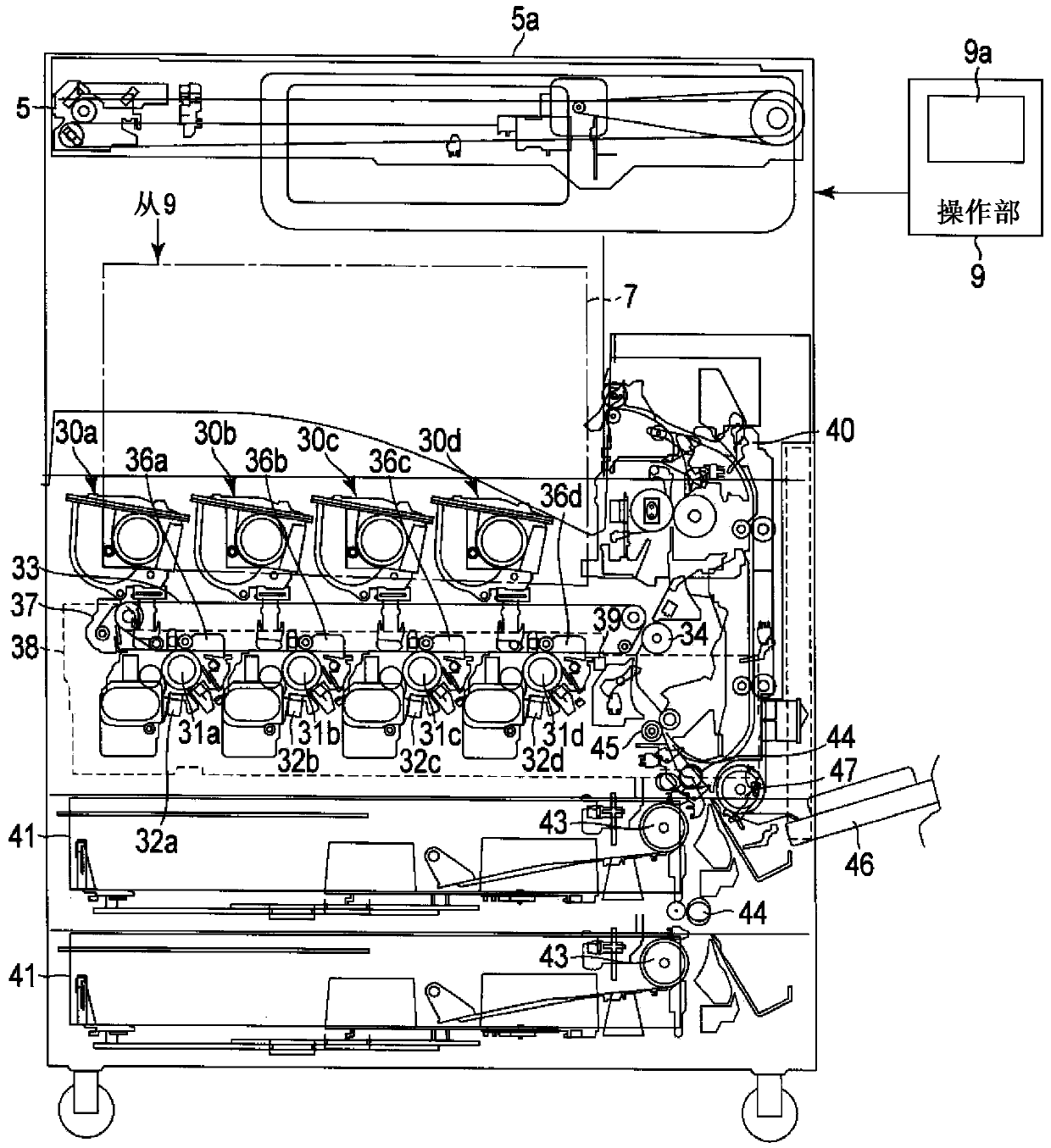
[0022] figure 1 The illustrated image forming apparatus (MFP (multi-function peripherals), hereinafter simply referred to as MFP) 1 includes at least an image forming unit 3 , an image reading unit 5 , and a signal processing / operation control unit (circuit board unit) 7. In addition, an operation unit (display panel) 9 is located at a predetermined position of the MFP 1 .

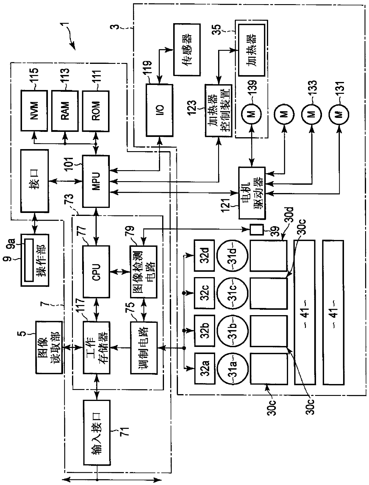
[0023] The image forming unit 3 forms a visible image corresponding to the image data on a sheet such as paper or a resin sheet. The image data may be, for example, data generated by the image reading unit 5 or external data. The data from the outside may be data supplied from a storage (removable) medium such as a semiconductor memory, or may be a supply source on the network via the interface 71 (refer to image 3 ) supplied data.

[0024] The image reading unit 5 acquires characters and images of the object to be read as b...


PUM


Abstract

The invention provides an image forming apparatus which enables timing optimization of latent image formation of an LED head according to an image including a chart and grids or the color of the image. A first exposure unit exposure unit includes a given number of light-emitting elements which are linearly arranged, and changes a light emission amount of each light-emitting element in response to an image signal corresponding to a first color which can hardly be recognized in the change of the straight line state. A first image carrier holds an image corresponding to the light emission amount of each light-emitting element of the first exposure unit. A second exposure unit includes a given number of light-emitting elements which are linearly arranged, and changes the light emission amount of each light-emitting element in response to an image signal corresponding to a second color which can be easily recognized in the change of the straight line state. A second image carrier holds an image corresponding to the light emission amount of each light-emitting element of the second exposure unit. An exposure signal generation unit excludes a correction during exposure for reducing the influence of the change of the straight line state of each light-emitting element at the time when the second exposure unit emits the light.

Description

technical field [0001] The present invention relates to an image forming apparatus. Background technique [0002] In an image forming apparatus that forms an image on a sheet, a method of visualizing a latent image formed by irradiating a photoreceptor with image light with a developing material (developer) is generally employed. [0003] There is an image forming apparatus that uses an LED (Liquid Emitting Diode: Light Emitting Diode) head as a device for irradiating image light to a photoreceptor. [0004] In an image forming apparatus using an LED head, a predetermined number of LED elements corresponding to a resolution are arranged linearly to form a linear image extending in the main scanning direction. In the sub-scanning direction perpendicular to the main-scanning direction, linear images extending in the main-scanning direction are sequentially formed at intervals determined according to the resolution. That is, an output image determined by the number of pixels ...

Claims


Application Information

Patent Timeline
Patent Type & Authority Applications(China)
IPC IPC(8): G03G15/043
CPCG03G15/04054G03G15/043
Inventor 市川正树
Owner KK TOSHIBA
Features
  • R&D
  • Intellectual Property
  • Life Sciences
  • Materials
  • Tech Scout
  • Unparalleled Data Quality
  • Higher Quality Content
  • 60% Fewer Hallucinations
Learn More