
air battery

An air battery and power collection technology, which is applied in the direction of batteries, hybrid batteries, battery pack components, etc., can solve the problems of inapplicability to vehicle power supplies and inability to connect directly to each other

Active Publication Date: 2017-03-22
NISSAN MOTOR CO LTD
View PDF6 Cites 0 Cited by
  • Summary
  • Abstract
  • Description
  • Claims
  • Application Information

AI Technical Summary

Problems solved by technology

However, since the above-mentioned conventional air batteries have a structure that cannot be directly connected to each other, there is a problem that they cannot actually be applied to vehicle-mounted power supplies.

Method used


Image

  • air battery
  • air battery
  • air battery

Examples


Embodiment Construction

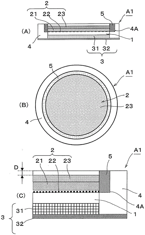
[0048] Hereinafter, embodiments of the air battery of the present invention will be described in detail based on the drawings.

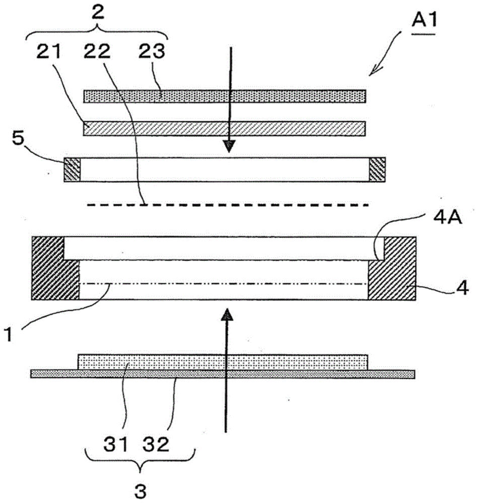
[0049] figure 1 The shown air battery A1 is disc-shaped, has a positive electrode layer 2 on the upper side in the figure and a negative electrode layer 3 on the lower side in the figure through an electrolyte layer 1, and has electrical insulation and surrounds at least the positive electrode layer 2 and the electrolyte. Frame member 4 on the outer periphery of layer 1 .

[0050] The positive electrode layer 2 includes, in a laminated state, a positive electrode member 21 , a positive electrode current collecting member 22 disposed on one surface of the positive electrode member 21 , and a liquid-tight gas-permeable member 23 disposed on the surface side of the positive electrode layer 2 . In the illustrated example, a positive electrode current collecting member 22 is provided on the electrolyte layer 1 side (lower side in the figure) of the posit...


PUM


Abstract

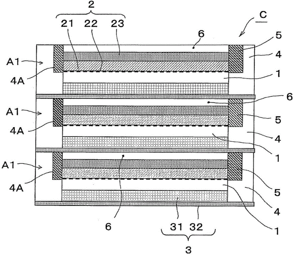
Conventional air batteries have a structure that cannot be directly connected to each other, and there is a problem that they cannot be applied to vehicle power supplies. The air battery (A1) of the present invention includes a positive electrode layer (2) and a negative electrode layer (3) with an electrolyte layer (1) interposed therebetween, and has an electrical insulating outer periphery surrounding the electrolyte layer (1) and the positive electrode layer (2). Outer frame member (4), positive electrode layer (2) is equipped with positive electrode member (21), positive electrode current collector member (22), and liquid-tight ventilation member (23), and negative electrode layer (3) is equipped with negative electrode member (31) With the negative electrode current collecting member (32), the positive electrode layer (2) is provided between the frame member (4) and the inner end portion is in contact with the peripheral portion of the positive electrode current collecting member (22), and the outer end portion is exposed on the positive electrode surface side. The contact part (5), the outer end of the contact part (5) protrudes from the surface of the liquid-tight ventilation part (23) and at least reaches the same level as the end face of the outer frame part (4), thereby , can realize direct series connection between batteries, and is suitable for vehicle power supply.

Description

technical field [0001] The present invention relates to an air battery using oxygen as the positive electrode active material, in particular to an air battery suitable for forming a battery pack composed of a plurality of connected batteries. Background technique [0002] As a conventional air battery, there is an air battery described in Patent Document 1, for example. The air battery described in Patent Document 1 has a structure in which an electrode group is formed by sandwiching a non-aqueous electrolyte layer between a positive electrode and a negative electrode, and the electrode group is accommodated in a storage case together with terminals of the positive electrode and the negative electrode. The two terminals protrude in opposite directions from the storage case. In addition, the air battery has a plurality of air holes in the positive electrode side wall of the storage case, and these air holes are blocked with a sealing tape. When in use, the air holes are open...

Claims


Application Information

Patent Timeline
Patent Type & Authority Patents(China)
IPC IPC(8): H01M12/06H01M50/51
CPCH01M12/065H01M12/08H01M2220/20H01M50/51Y02E60/10
Inventor 宫泽笃史长山森塚田佳子千叶启贵
Owner NISSAN MOTOR CO LTD
Learn More