Air-bag type jack

A jack and airbag type technology, which is applied in the direction of lifting devices, etc., can solve the problems of shaking, unsmooth rise and fall, and inability to take out the airbag type jack.

Inactive Publication Date: 2014-08-13
赖华东
View PDF10 Cites 7 Cited by
  • Summary
  • Abstract
  • Description
  • Claims
  • Application Information

AI Technical Summary

Problems solved by technology

However, the inside of the airbag of the airbag jack uses the inner shaft sleeve to limit the position. The processing technology requirements of the inner shaft sleeve are high, and the raw material cost of the seamless pipe used is also high. However, in actual use, due to the weight of the car after being jacked The offset of the airbag jack

Method used


Image

  • Air-bag type jack
  • Air-bag type jack
  • Air-bag type jack

Examples


Embodiment 1

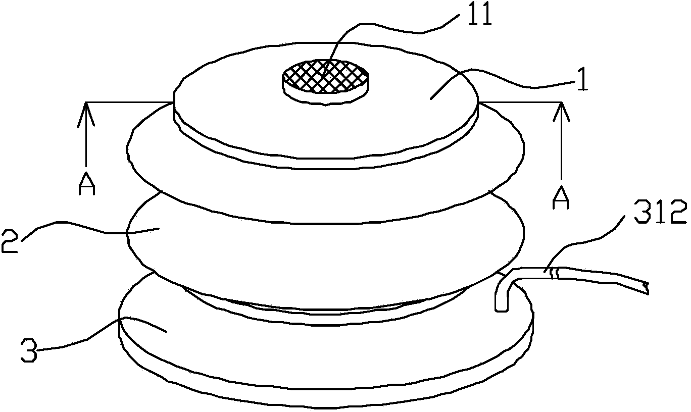
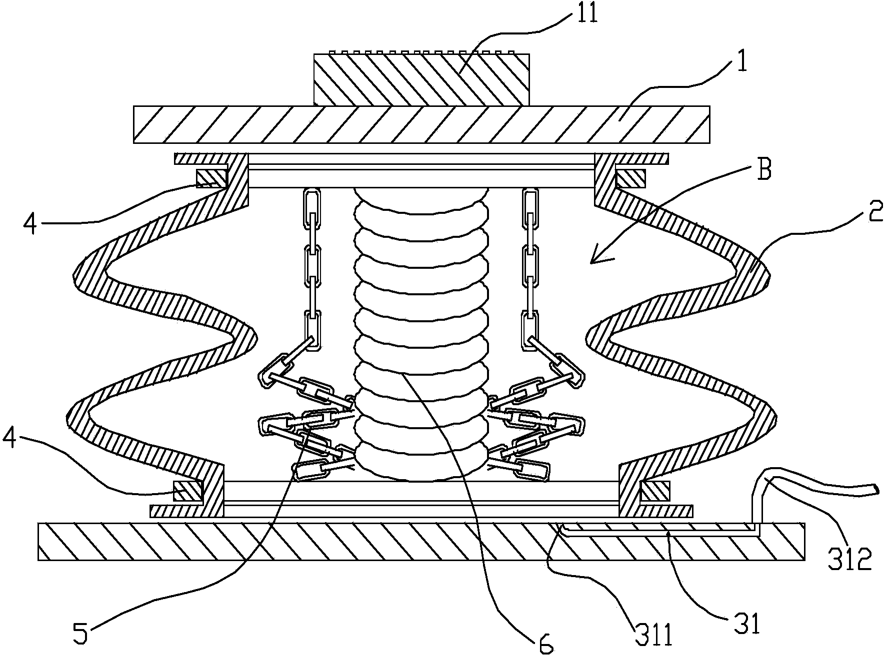
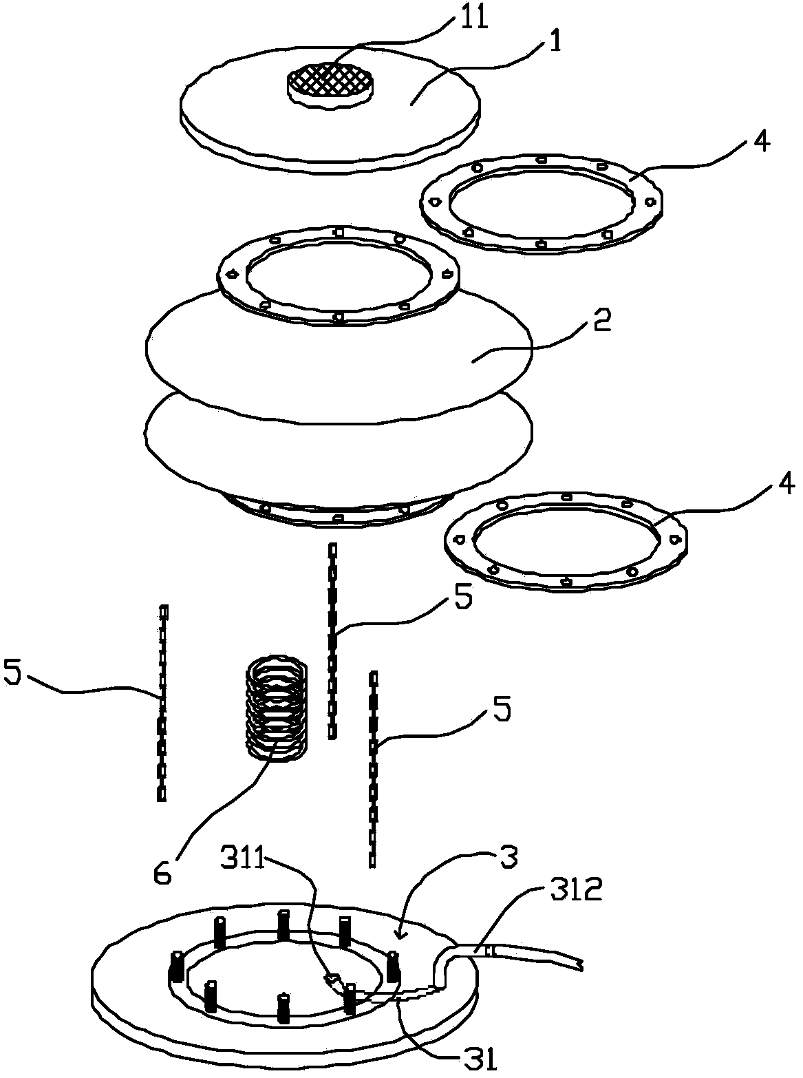
[0022] Figure 1 to Figure 3 A balloon jack according to one embodiment of the present invention is shown schematically. As shown in the figure, the device includes an upper top plate 1, a lower bottom plate 3, a rubber airbag 2 and a flange 4. The two ends of the rubber airbag 3 are sealedly connected to the upper top plate 1 and the lower bottom plate 3 through two flanges 4 respectively. The rubber airbag 2 A closed cavity B is thus formed inside.

[0023] A shock absorbing plate 11 is fixed on the upper top plate 1 .

[0024] The lower bottom plate 3 is connected to the high pressure air source through the air intake pipe 312 . An air inlet 31 is arranged in the lower bottom plate 3, and an air outlet 311 is arranged in the bag cavity B. The air intake pipe 312 is communicated with the air outlet 311 through the air intake passage 31 .

[0025] A balance limiting device is also provided inside the bladder cavity B.

[0026] In this embodiment, the balance limiting dev...

Embodiment 2

[0030] Figure 4 A balloon jack according to another embodiment of the present invention is schematically shown. The difference from Embodiment 1 is that a strap 7 is also included. As shown in the figure, the strap 7 bypasses the upper top plate 1 and is fixedly connected to the lower bottom plate 3 at both ends. In this embodiment, a hole and slot for the strap 7 to pass through is provided between the shock absorbing plate 11 and the upper top plate 1 . The straps 7 are not connected with the upper top plate 1 , and when the rubber airbag 2 rises, the straps 7 can slide on the upper top plate 1 , thereby achieving the purpose of keeping the upper top plate 1 in a balanced state. The strap 7 used in this embodiment is an industrial strength strap that can bear a force exceeding 2 tons.

[0031] In other embodiments, the balance limiting device may also be a strap 7 . When the air bag type jack works, the strap 7 slides on the upper top plate 1 , which can also ensure that...

Embodiment 3

[0034] Figure 5 A balloon jack according to yet another embodiment of the present invention is schematically shown. The difference from Embodiment 1 is that it also includes a control rod 8 and a heightening block 9 .

[0035] As shown in the figure, the height-increasing block 9 is placed on the upper top plate 1 to increase the lifting height of the air-bag type jack.

[0036] The control rod 8 is connected with the lower bottom plate 3 and includes a handrail 82 and a hollow straight rod 81 . The handrail 82 is arranged on one end of the straight rod 81 . The other end of the straight rod 81 is provided with a small wheel 83 . The air intake pipe 312 is penetrated inside the straight rod 81 .


PUM


Abstract

The invention discloses an air-bag type jack. The air-bag type jack comprises an upper top plate, a lower bottom plate, a rubber air bag and flanges, wherein the lower bottom plate is connected with an external high-pressure air source by an air inlet pipe; the two ends of the rubber air bag are connected with the upper top plate and the lower bottom plate by two flanges in a sealing manner, respectively; a sealed bag cavity is formed in the rubber air bag and is internally provided with an air outlet; an air inlet channel is arranged in the lower bottom plate; the air outlet is communicated with the air inlet pipe by the air inlet channel; the lower bottom plate is provided with a balance limiting device. The air inlet channel is arranged in the lower bottom plate, so that the condition that the air inlet device is arranged on the rubber air bag and causes ununiform stress on the rubber air bag to lower the bearing capability of the rubber air bag can be avoided. Therefore, the air-bag type jack disclosed by the invention has the advantages that the bearing load is large and the rubber air bag is not easily perforated to cause explosion.

Description

technical field [0001] The invention relates to a jack, in particular to an air bag type jack. Background technique [0002] Existing jacks have various structural forms, including pneumatic or hydraulic operation modes. Among them, pneumatic jacks are also called bladder-type jacks because they have an air bag that can be filled with compressed air. [0003] The structure of the air bag type jack is relatively simple, and it only needs to provide compressed air to work. [0004] At present, air bag jacks also have different structures. For example, the invention with publication number CN102774779A discloses an air bag jack, which includes a base, an air bag is arranged on the base, a support assembly is arranged on the upper end of the air bag, and an energy source is arranged in the air bag. An inner sleeve that keeps the airbag vertically stable and can be retracted, one end of the inner sleeve is fixedly connected to the base, and the other end of the inner sleeve is c...

Claims


Application Information

Patent Timeline
IPC IPC(8): B66F3/35
Inventor 赖华东
Owner 赖华东
Why Eureka
Try Eureka