Lifting device

A technology of lifting device and lifting arm, applied in the direction of lifting device, lifting frame, etc.

Active Publication Date: 2014-08-13
SUZHOU TIANYE MEDICAL EQUIP CO LTD
View PDF10 Cites 22 Cited by
  • Summary
  • Abstract
  • Description
  • Claims
  • Application Information

AI Technical Summary

Problems solved by technology

[0002] In equipment that needs to be lifted, such as aerial work lifting platforms and medical beds, scissor-type lifting mechanisms are usually used to lift the work platforms or medical beds. Typical scissor-type lifting mechanisms are as follows: figure 1 As shown, it includes a platform 100, an underframe 200 and a lifting frame 300 between the two. The lifting frame 300 includes two connecting rods arranged in a cross-scissor structure. The two connecting rods are hinged at the middle intersection point, one of which is The upper end of the rod is hinged with the platform 100, the lower end is slidingly connected with the chute on the bottom frame 200, the upper end of the other connecting rod is slidably connected with the chute on the platform 100, and the lower end is hinged with the bottom frame 200, by horizontally pushing the lower part of the connecting rod The sliding end, the vertical push platform 100 or the inclined push link can all realize the lifting of the platform 100, such as the "mobile lifting loading and unloading platform" disclosed in Chinese patent CN2861115

Method used


Image

  • Lifting device
  • Lifting device
  • Lifting device

Examples


Embodiment Construction

[0028] The specific implementation manner of the present invention will be described below in conjunction with the accompanying drawings.

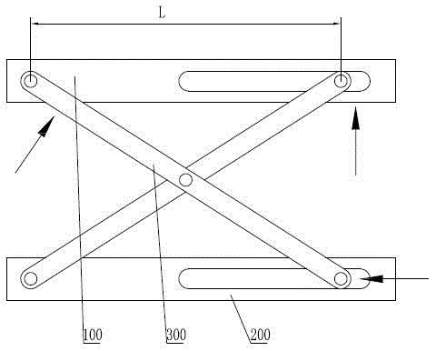
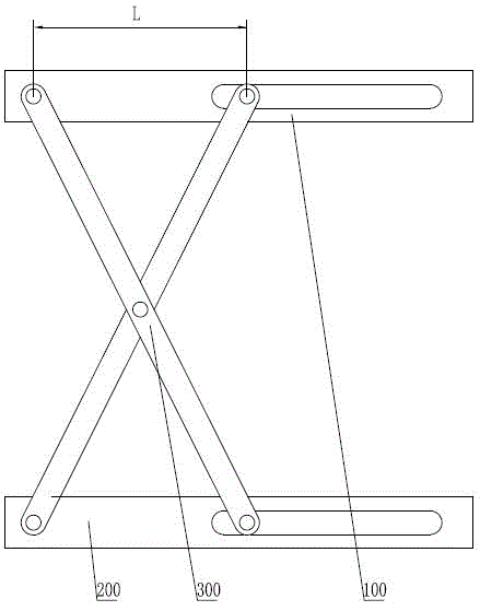
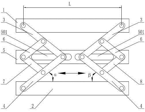
[0029] See image 3 , Figure 4 , the present invention includes a top seat 1 and a base 2, two movable support frames arranged in a staggered manner along the length direction of the top seat 1 are arranged between the top seat 1 and the base 2, and any one of the movable support frames includes an upper frame arranged in a V-shaped structure. Lifting arm 3 and lower lifting arm 4, the upper end of upper lifting arm 3 is hinged with top base 1, the lower end of lower lifting arm 4 is hinged with base 2, the lower end of upper lifting arm 3 and the upper end of lower lifting arm 4 are hinged on the same pin shaft, And the hinge pins of the two are slidingly connected with the chute 501 on the intermediate frame 5, and the intermediate frame 5 is provided with two chute 501 corresponding to the two movable support frames; 6 The other end ...


PUM


Abstract

A lifting device comprises an ejection seat, a base and two movable supporting frames between the ejection seat and the base, wherein the movable supporting frames comprise upper and lower lifting arms respectively hinged to the ejection seat and the base, and the sliding ends of the upper and lower lifting arms are in sliding connection with a middle frame upper chute through the same hinge pin. Upper and lower pull rods are respectively hinged to the upper and lower lifting arms and hinged to a middle frame through the same hinge pin, the upper and lower lifting arms and the upper and lower pull rods are symmetrically arranged on upper and lower sides of the middle frame, connecting lines formed by two hinge centers of the upper pull rods are parallel, the length is one half of the length of connecting lines of two-end hinge centers of the lower lifting arms, connecting lines formed by two hinge centers of the lower pull rods are parallel, the length is one half of the length of connecting lines of two-end hinge centers of the upper lifting arms. A driving device drives the upper and lower lifting arms in the movable supporting frames to move along a chute in the middle frame to achieve ejection seat lifting. Supporting separation distances of the lifting arms on the ejection seat are invariant, and required pushing force when the ejection seat is lifted from the lowest position is small.

Description

technical field [0001] The invention relates to a working platform or a lifting bed with a lifting function. Background technique [0002] In equipment that needs to be lifted, such as aerial work lifting platforms and medical beds, scissor-type lifting mechanisms are usually used to lift the work platforms or medical beds. Typical scissor-type lifting mechanisms are as follows: figure 1 As shown, it includes a platform 100, an underframe 200 and a lifting frame 300 between the two. The lifting frame 300 includes two connecting rods arranged in a cross-scissor structure. The two connecting rods are hinged at the middle intersection point, one of which is The upper end of the rod is hinged with the platform 100, the lower end is slidingly connected with the chute on the bottom frame 200, the upper end of the other connecting rod is slidably connected with the chute on the platform 100, and the lower end is hinged with the bottom frame 200, by horizontally pushing the lower pa...

Claims


Application Information

Patent Timeline
IPC IPC(8): B66F7/06B66F7/28
Inventor 黄卉
Owner SUZHOU TIANYE MEDICAL EQUIP CO LTD
Why Eureka
Try Eureka