
Support member

A technology of supporting components and supporting rods, which is applied in the direction of supporting machines, machine tables/brackets, shock absorbers, etc., can solve the problems of glass substrate support, etc., and achieve the effect of length attenuation compensation and flexible adjustment

Active Publication Date: 2014-08-13
TCL CHINA STAR OPTOELECTRONICS TECH CO LTD
View PDF6 Cites 3 Cited by
  • Summary
  • Abstract
  • Description
  • Claims
  • Application Information

AI Technical Summary

Problems solved by technology

At this time, the above-mentioned ejector mechanism cannot effectively support the glass substrate.

Method used


Image

  • Support member
  • Support member
  • Support member

Examples


Embodiment Construction

[0026] The following descriptions of the various embodiments refer to the accompanying drawings to illustrate specific embodiments in which the present invention can be practiced.

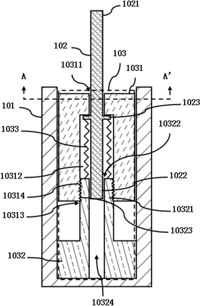
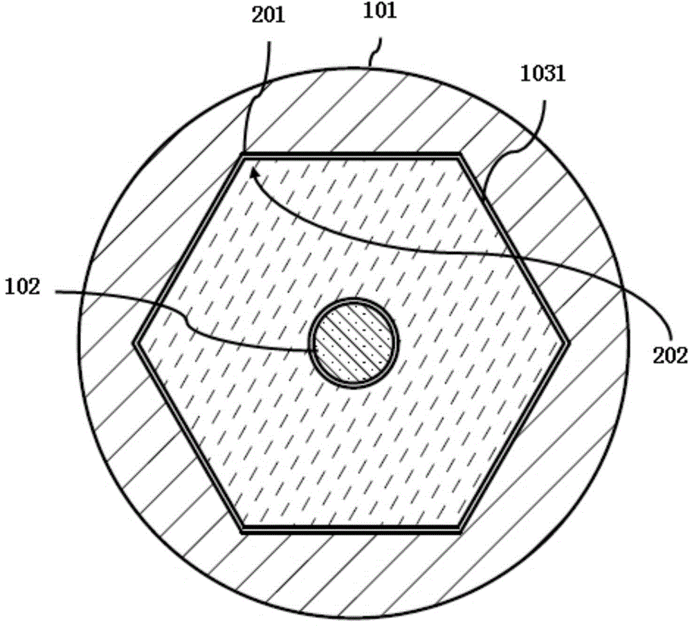
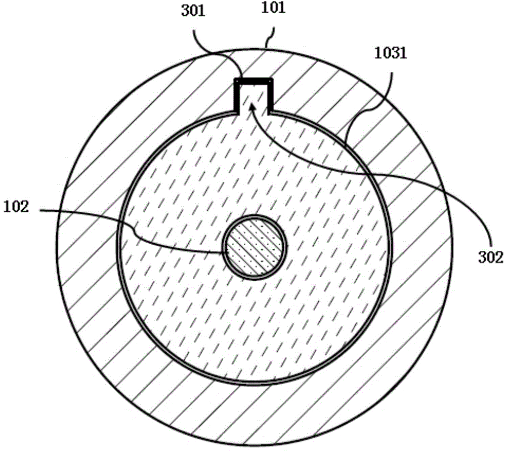
[0027] refer to figure 1 , figure 2 and image 3 , figure 1 is a schematic diagram of the first embodiment of the support member of the present invention, figure 2 for figure 1 The schematic diagram of the first embodiment of the A-A' section in the middle, image 3 for figure 1 Schematic diagram of the second embodiment of the section A-A' in the middle.

[0028] The supporting member in this embodiment includes a housing 101 , a supporting rod 102 and an adjusting member 103 . Wherein, the casing 101 may be configured in a tubular shape. The support rod 102 has a first end 1021 and a second end 1022 , the support rod 102 has an engaging portion 1023 , and the engaging portion 1023 is located between the first end 1021 and the second end 1022 . The locking part 1023 can be a buckle (for...


PUM


Abstract

The invention discloses a support member. The support member comprises a shell, a support rod provided with a first tail end and a second tail end, and a regulation member; the support rod is provided with a clamping part which is arranged between the first tail end and the second tail end; the regulation member is connected in the shell in a sleeving mode; the regulation member is provided with a containing chamber and a first through hole connected with the containing chamber; a spring is arranged in the containing chamber; the support rod penetrates through the first through hole; the clamping part of the support rod is arranged in the containing chamber; the first tail end of the support rod is exposed out of the regulation part; the second tail end of the support rod penetrates through the spring; the clamping part is in contact with the spring. The shape of the cross section of the shell corresponds to the shape of the cross section of the regulation part. The regulation on the compression amount of the spring is realized by the support member, so the compensation for the length attenuation of the spring is realized.

Description

【Technical field】 [0001] The invention relates to the technical field of display panel production, in particular to a support member. 【Background technique】 [0002] In the display panel production line, machines with a stage generally use a lift pin mechanism, which is used to allow a robot arm to move glass substrates in or out of the stage. With the development of display panel technology, the area of ​​the glass substrate is getting larger and the thickness is getting thinner, and the speed of handling the glass substrate is getting faster and faster. In this case, the probability of breaking the glass substrate increases accordingly. [0003] In order to reduce the risk of breaking the glass substrate, the existing solution is to add a spring to the ejector mechanism to buffer the glass substrate. [0004] In practice, the inventors found that the prior art has at least the following problems: [0005] After a period of use, the elasticity of the above-mentioned sprin...

Claims


Application Information

Patent Timeline
Patent Type & Authority Applications(China)
IPC IPC(8): F16M11/26F16F7/104
Inventor 区炜锋梁元豪刘丽军
Owner TCL CHINA STAR OPTOELECTRONICS TECH CO LTD
Learn More