Head mounted display, control method for head mounted display, and image display system
一种头戴式显示、图像显示的技术,应用在立体系统、图像通信、数据处理的输入/输出过程等方向,能够解决不同、不能够自动跟踪被摄体、不能拍摄等问题
- Summary
- Abstract
- Description
- Claims
- Application Information
AI Technical Summary
Problems solved by technology
Method used
Image

Examples
Embodiment approach
[0053] A-1. Composition of shooting system:
[0054] A-2. Composition of the head-mounted display device:
[0055] A-3. Image display processing of the position of the subject:
[0056] B. Other implementation methods:
[0057] C. Variations:
[0058] A. Implementation method:
[0059] A-1. Composition of shooting system:
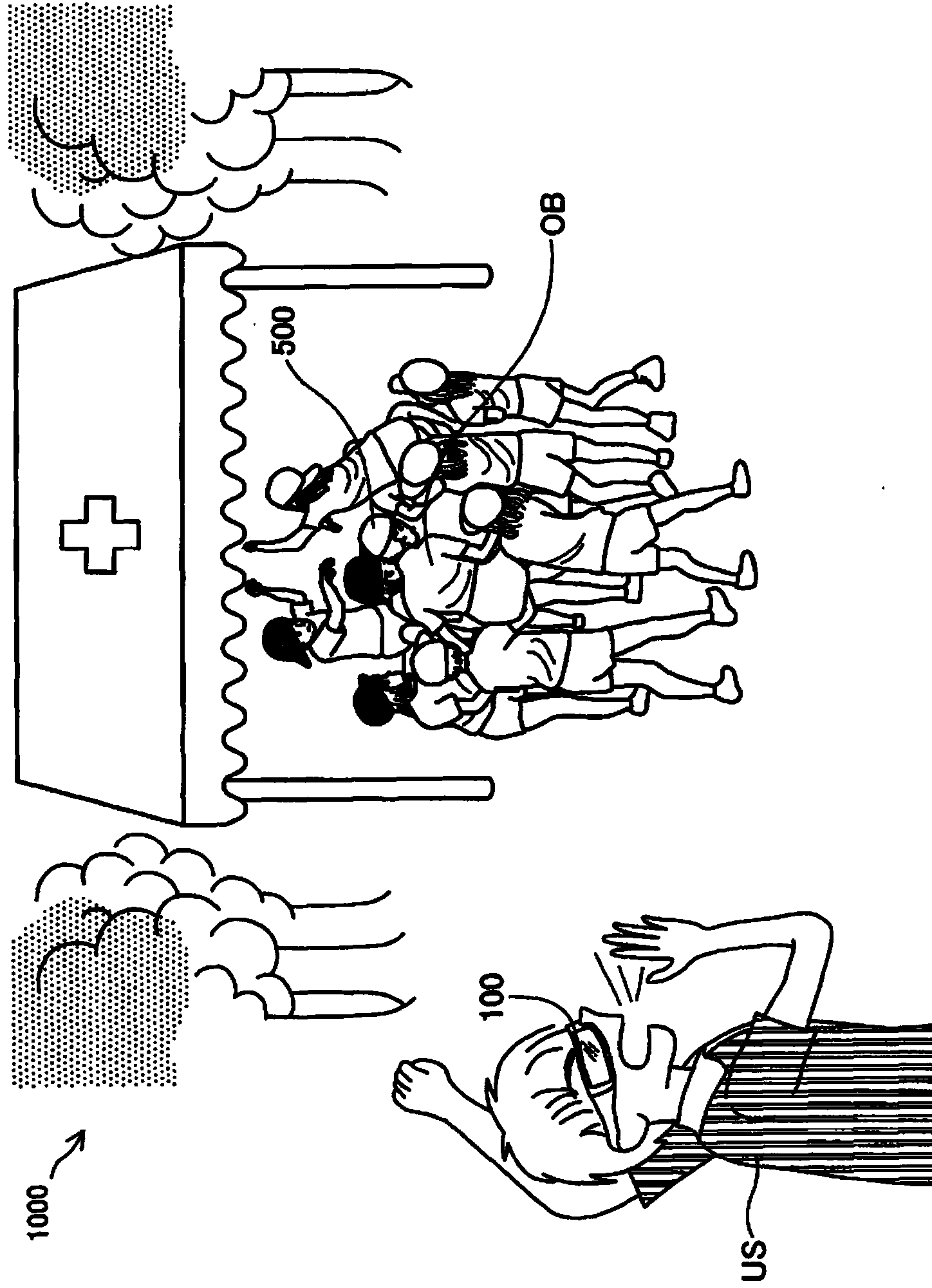
[0060] figure 1 It is an explanatory diagram showing a schematic configuration of the imaging system 1000 in the embodiment of the present invention. exist figure 1 In the photographing system shown, in a sporting event, a user US of a head-mounted display device 100 (details will be described later) performs an inspection on an object OB wearing an object position determining device 500 for determining the position of the object OB. shoot. The imaging system 1000 includes a subject position specifying device 500 and a head-mounted display device 100 . The subject position determining device 500 is formed in a hat worn on the head of the subject OB...
Deformed example 1
[0130] In the above embodiment, if Figure 12 As shown, the bird's-eye view VI1 and the captured image VI2 are displayed in the lower right area when the largest image display area PN is divided into nine equal parts. out of shape. Figure 13 It is an explanatory diagram showing an example of the field of view VR visually recognized by the user US. exist Figure 13 , and the above embodiment in the Figure 12 The illustrated diagrams are different in that the position where the captured image VI2 is displayed in the largest image display area PN is different. In the head-mounted display device 100 of this modified example, the control unit 10 sets the position where the captured image VI2 is displayed in the largest image display area PN to A position not overlapping the subject OB is set in the largest image display area PN. Therefore, in the head-mounted display device 100 of this modified example, the user US can always visually recognize the subject OB of the external...
Deformed example 2
[0134] In the above-described embodiment, the image showing the position of the object OB displayed in the largest image display area PN and the position of the image in the largest image display area PN are changed based on the relative position of the object OB with respect to the user US. , but the image and the position where the image is displayed are not limited to this, and various modifications can be made. Figure 14 It is an explanatory diagram showing an example of the field of view VR visually recognized by the user US. Such as Figure 14 As shown, in a portion including the center of the largest image display area PN, an arrow MK4 as an image indicating the position of the object OB is displayed. exist Figure 14 , the field of view VR of the user US does not include the subject OB, and the arrow MK4 indicates that the subject OB is located on the right side of the user US. In the head-mounted display device 100 of this modified example, when the subject OB is ...
PUM
 Abstract
Description
Claims
Application Information
 - R&D Engineer
- R&D Manager
- IP Professional
- Industry Leading Data Capabilities
- Powerful AI technology
- Patent DNA Extraction
Browse by: Latest US Patents, China's latest patents, Technical Efficacy Thesaurus, Application Domain, Technology Topic.
© 2024 PatSnap. All rights reserved.Legal|Privacy policy|Modern Slavery Act Transparency Statement|Sitemap