Inverted charging injection mould charged with glue from rear die

An injection mold and back mold technology, applied in the field of flip-chip injection molds, can solve the problems of cavity surface punching into pits, fog generation, irregularities, etc., to improve the quality of surface structure, prolong service life, and reduce maintenance costs. Effect

Active Publication Date: 2014-08-20
SHENZHEN SKYWORTH RGB ELECTRONICS CO LTD
View PDF3 Cites 2 Cited by
  • Summary
  • Abstract
  • Description
  • Claims
  • Application Information

AI Technical Summary

Problems solved by technology

[0003] 1) The injection point of the flip-chip mold directly impacts the surface of the cavity, and the surface of the cavity is washed in a short time. After a long time, the surface of the cavity will be washed into pits. After the cavity is washed, it needs to be repaired frequently. After that, welding is required, and welding will affect the local material change of the cavity, which will affect the quality of the injection molded product and the service life of the mold.
[0004] 2) At present, the surface of the cavity of the flip-chip mold is directly subjected to high temperature, high pressure, and high-speed plastic impact, and the surface of the cavity is cooled rapidly after high temperature, and steam is heated again to cause fog on the surface of the cavity. When the next time After high-temperature, high-pressure, and high-speed plastics, the mist cannot be discharged in time, and there will be fog-like flow marks on the surface of the formed product (very obvious when viewed from the side), and it is very irregular
Especially when there is an etched structure on the surface of the cavity, it is more obvious, and the mist is difficult to discharge out of the cavity, and the outer surface of the injection molded product is even more defective.

Method used


Image

  • Inverted charging injection mould charged with glue from rear die
  • Inverted charging injection mould charged with glue from rear die
  • Inverted charging injection mould charged with glue from rear die

Examples


Embodiment Construction

[0025] The present invention provides a flip-chip injection mold with glue fed from the back mold. In order to make the purpose, technical solution and advantages of the present invention clearer and clearer, the present invention will be further described in detail below with reference to the accompanying drawings and examples. It should be understood that the specific embodiments described here are only used to explain the present invention, not to limit the present invention.

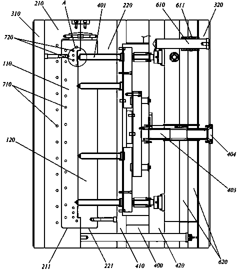
[0026] See figure 1 , figure 1 It is a structural schematic diagram of a flip-chip injection mold that feeds glue from the rear mold in the present invention.

[0027] Such as figure 1 As shown, the flip-chip injection mold that feeds glue from the rear mold includes:

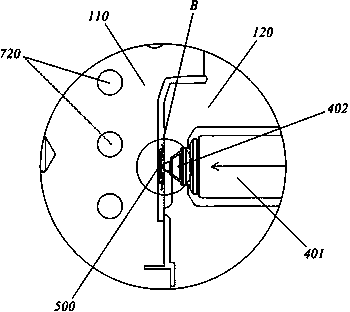
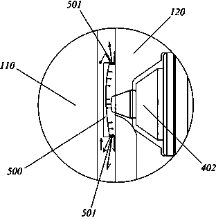
[0028] The front mold cavity 110 and the rear mold core 120 are oppositely arranged, and the front mold cavity 110 is fixed on the upper code template 310 through the front mold frame 210, and the rear mold core 120 is fixed on the...


PUM

PropertyMeasurementUnit
diameteraaaaaaaaaa

Abstract

The invention discloses an inverted charging injection mould charged with glue from a rear die, and the inverted charging injection mould comprises a front die cavity and a rear die core which are arranged oppositely, the front die cavity is fixed on an upper code template by a front die frame, the rear die core is fixed on a lower code template by a rear die frame, a hot runner spreader plate is arranged between the rear die core and the lower code template, a heat division runner sequentially passing through the rear die frame and the rear die core is arranged on the hot runner spreader plate, a glue injection nozzle extending into the front die cavity is arranged at the end of the heat division runner; the front end of the nozzle is provided with a buffer plate; the baffle plate is used for transferring and injecting high temperature, high pressure and high speed melt glue injected from the glue injection nozzle onto the rear die core, and avoids the direct impact of the cavity and damage of highlight surface, texuring surface or pattern surface of the cavity surface by impact, so that the mould maintenance cost can be reduced, the mould service life can be prolonged, fog phenomenon generating on the cavity surface can be solved, and the surface structure quality of injection molding products can be improved.

Description

technical field [0001] The invention relates to an injection mold, in particular to a flip-chip injection mold in which glue is fed from a rear mold. Background technique [0002] Since the invention of the injection mold, the glue inlet matching the injection molding machine basically feeds the glue from the direction of the cavity, but with the advancement of technology, some injection molds begin to feed the glue from the direction of the core. Compared with the former, it is called flip chip for short. mold. However, injecting glue from the core still has some technical defects, and the molded products still have certain shortcomings, which are summarized as follows: [0003] 1) The injection point of the flip-chip mold directly impacts the surface of the cavity, and the surface of the cavity is washed in a short time. After a long time, the surface of the cavity will be washed into pits. After the cavity is washed, it needs to be repaired frequently. After that, weldi...

Claims


Application Information

Patent Timeline
Patent Type & Authority Applications(China)
IPC IPC(8): B29C45/27B29C45/73
CPCB29C45/27B29C45/372B29C45/73
Inventor 王学敏
Owner SHENZHEN SKYWORTH RGB ELECTRONICS CO LTD
Why Eureka
Try Eureka