Auger conveyor

An auger conveyor and machine body technology, applied in the field of conveyors, can solve the problems of easy blockage of the discharge port, low conveying capacity, and heavy workload, and achieve the effects of increasing conveying distance, simple equipment maintenance, and high utilization rate

Inactive Publication Date: 2014-08-27
QUECHEN SILICON CHEM
View PDF7 Cites 4 Cited by
  • Summary
  • Abstract
  • Description
  • Claims
  • Application Information

AI Technical Summary

Problems solved by technology

[0002] The structure of the shaft auger conveyor currently used is relatively complicated
First of all, it adds three bearings, which is cumbersome to repair and maintain, with a large workload and high cost; secondly, due to the setting of the suspension bearing, the transported materials are easy

Method used


Image

  • Auger conveyor

Examples


Embodiment Construction

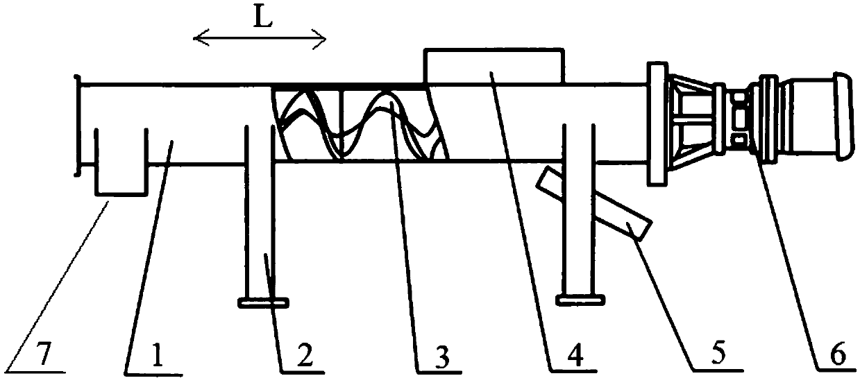
[0014] The auger conveyor of the present invention is now described with reference to the accompanying drawings, wherein figure 1 It is a structural schematic diagram of the auger conveyor of the present invention.

[0015] Such as figure 1 As shown, the auger conveyor of the present invention includes a machine body 1 , a driving device 6 and at least one shaftless helical blade 3 . Wherein, the driving device 6 is arranged at the end of the body 1 , and the shaftless helical blade 3 is arranged in the body 1 and connected with the driving device 6 , so that the shaftless helical blade 3 is driven to rotate in the body 1 by the driving device 6 . Specifically, all the shaftless helical blades 3 extend rotatably along the axial direction L of the machine body 1 . That is to say, the shaftless helical blades 3 are located inside the machine body 1 and driven to rotate by the driving device 6 , and the axes of the shaftless helical blades 3 coincide with the axial direction L ...


PUM


Abstract

The invention provides an auger conveyor. The auger conveyor comprises a machine body (1), a driving device (6) which is arranged on the end portion of the machine body (1) and at least one shaftless spiral blade (3) which is arranged inside the machine body (1) and connected with the driving device (6); the shaftless spiral blade (3) extends along the axis direction (L) of the machine body (1) in a rotatable mode. The auger conveyor can effectively convey materials being high in viscosity.

Description

technical field [0001] The present invention relates to the field of conveyors, more specifically, to an auger conveyor. Background technique [0002] The structure of the currently used shaft auger conveyor is relatively complicated. First of all, it adds three bearings, which is cumbersome to repair and maintain, with a large workload and high cost; secondly, due to the setting of the suspension bearing, the transported materials are easy to be entangled, and some high-viscosity, entangled or wet materials cannot be transported; in addition, the discharge The mouth is easy to block, the transmission is unstable, and the energy consumption is high; and the shaft auger conveyor has low conveying capacity and short conveying distance. Contents of the invention [0003] In view of the problems existing in the related art, the object of the present invention is to provide an auger conveyor capable of effectively conveying materials with high viscosity. [0004] To achieve t...

Claims


Application Information

Patent Timeline
IPC IPC(8): B65G33/14B65G33/26
Inventor 夏洪庆王永庆
Owner QUECHEN SILICON CHEM
Why Eureka
Try Eureka