Spraying machine and air supply spraying device thereof

A spray device and air supply technology, applied in the field of high-efficiency air supply spray devices, can solve the problems of poor uniformity of wind speed, small wind conveying distance of fans, large loss of air volume, etc. The effect of uniform performance improvement

Active Publication Date: 2012-11-21
NANTONG GUANGYI ELECTROMECHANICAL CO LTD
View PDF7 Cites 5 Cited by
  • Summary
  • Abstract
  • Description
  • Claims
  • Application Information

AI Technical Summary

Problems solved by technology

This kind of structure has relatively large air volume loss, poor wind speed uniformity, small wind conveying distance of fans of the same power, poor penetration ability of wind conveyed fog droplets between leaves, low utilization rate of pesticides, and poor control effect

Method used


Image

  • Spraying machine and air supply spraying device thereof
  • Spraying machine and air supply spraying device thereof
  • Spraying machine and air supply spraying device thereof

Examples


Embodiment Construction

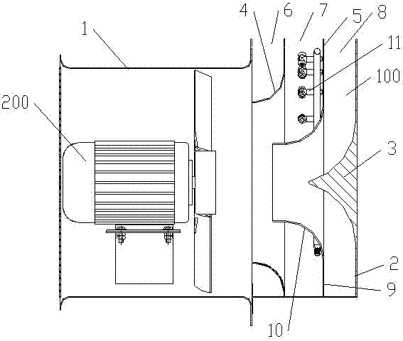
[0022] see figure 1 The sprayer includes a wind spraying device 100 and an axial flow fan 200 arranged in the axial flow cylinder.

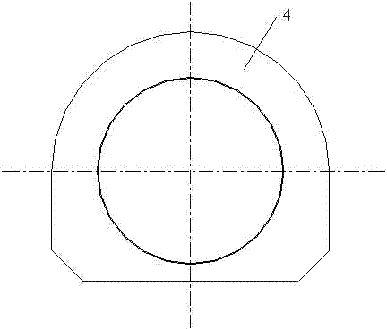
[0023] The air-driven spraying device includes a back plate 2 opposite to the outlet of the axial flow air cylinder 1, and a guide cone 3 coaxial with the axial flow air cylinder is arranged on the back plate. The back plate 2 and the deflector cone 3 are integral to form a windshield. A first flow guide plate 4 and a second flow guide plate 5 are also arranged between the axial fan cylinder and the back plate. 5 and the diversion guide of diversion cone 3 form three parts of radial airflow. The three radial airflows flow out from the first, second and third air outlets 6, 7 and 8 respectively. The first air outlet 6 is formed between the housing of the axial fan cylinder and the first diversion guide plate; the second air outlet 7 is formed between the first diversion guide plate and the second diversion guide plate, and the second diversion ...


PUM


Abstract

The invention provides an air supply spraying device capable of improving uniformity of air speed of a whole outlet to reduce dispersion of (radial) air force of the outlet and accordingly improving an effective conveying distance of fogdrop. The air supply spraying device comprises a back plate opposite to an axial flow air barrel outlet, wherein a flow guiding cone coaxial with an axial flow air barrel is arranged on the back plate. A first branch guiding plate and a second branch guiding plate are further arranged between the axial flow air barrel and the back plate, axial flows flowing out of the axial flow air barrel form three parts of radial air flows under the drainage and guiding of the first branch guiding plate, the second branch guiding plate and the flow guiding cone. The three parts of radial air flows respectively flows out of the position between a casing of the axial flow air barrel and the first branch guiding plate, the position between the first branch guiding plate and the second branch guiding plate and the position between the second branch guiding plate and the back plate. A spray head for spraying is arranged between the first branch guiding plate and the second branch guiding plate.

Description

technical field [0001] The invention relates to a sprayer, in particular to a high-efficiency wind-driven spraying device for an orchard sprayer. Background technique [0002] Existing various types of orchard air-driven sprayers are more traditional and single in structure. Generally, it is a single air outlet or a two-split air outlet. This kind of structure has relatively large air volume loss, poor wind speed uniformity, small wind conveying distance of fans of the same power, poor penetration ability of wind conveyed fog droplets between leaves, low utilization rate of pesticides, and poor control effect. Contents of the invention [0003] The purpose of this technology is to provide a wind-driven spray device that can improve the uniformity of the entire outlet wind speed to reduce the scattering of the outlet (radial) wind force, thereby increasing the effective delivery distance of the droplets. [0004] The air-driven spraying device includes a back plate opposi...

Claims


Application Information

Patent Timeline
Patent Type & Authority Applications(China)
IPC IPC(8): A01M7/00
Inventor 周宏平许林云郁金
Owner NANTONG GUANGYI ELECTROMECHANICAL CO LTD
Why Eureka
Try Eureka