Rail-type reciprocating conveying trolley

A reciprocating, transport vehicle technology, applied in the direction of transportation and packaging, conveyors, mechanical conveyors, etc., can solve the problems of consuming manpower and material resources, low efficiency, time-consuming and laborious, and achieve the effect of saving manpower and improving efficiency

Active Publication Date: 2014-08-27
POWERCHINA SEPCO1 ELECTRIC POWER CONSTR CO LTD
View PDF8 Cites 12 Cited by
  • Summary
  • Abstract
  • Description
  • Claims
  • Application Information

AI Technical Summary

Problems solved by technology

[0002] Due to the special design location of some equipment in thermal power plants, large machinery and transport vehicles cannot be transported to the installation site. In the past, roller-bar consignment was used, which was time-consuming, laborious, and inefficient.

Method used


Image

  • Rail-type reciprocating conveying trolley
  • Rail-type reciprocating conveying trolley
  • Rail-type reciprocating conveying trolley

Examples


Embodiment Construction

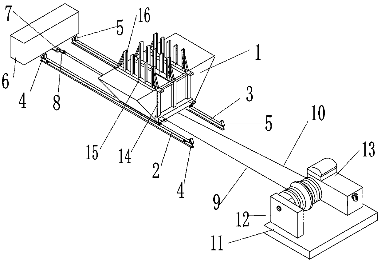
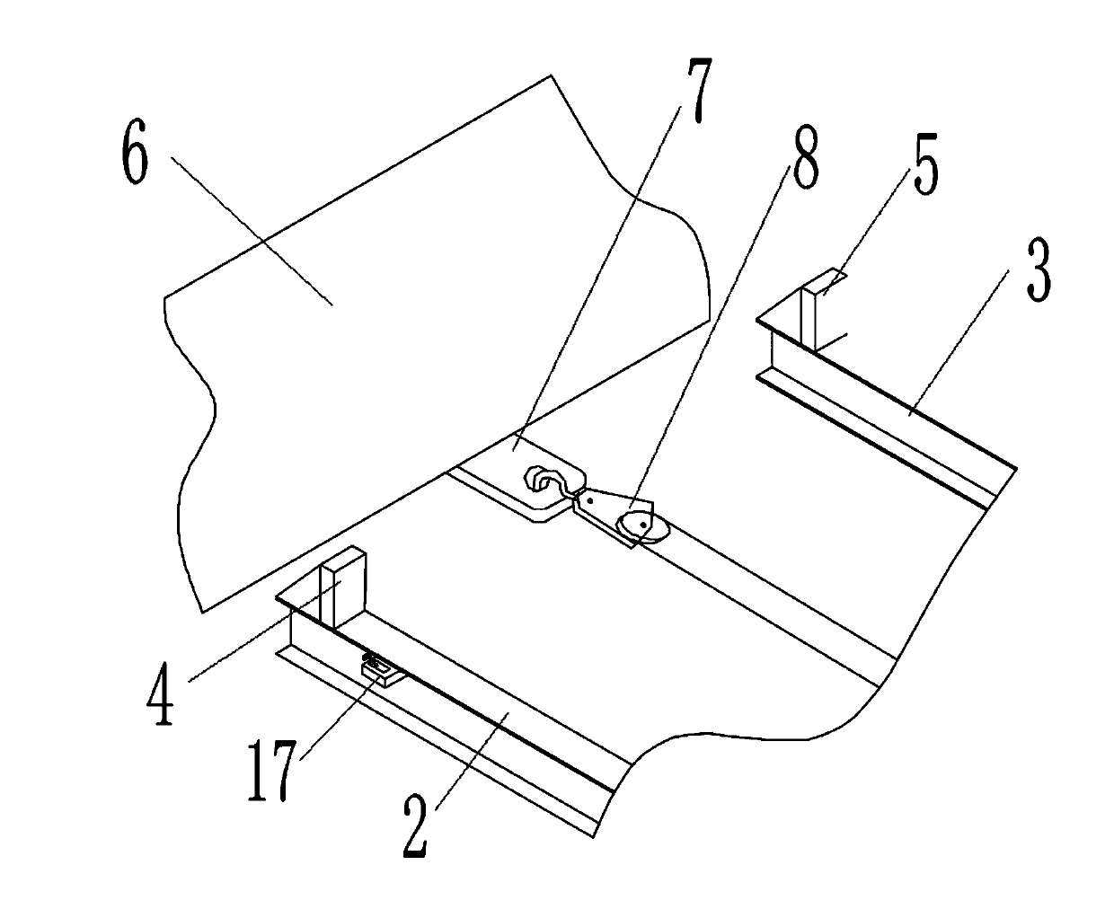
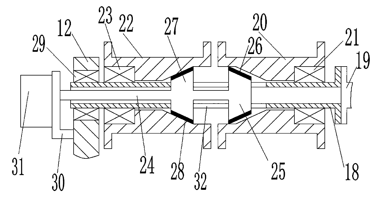
[0016] Attached below figure 1 , attached figure 2 , attached image 3 The present invention will be further described.

[0017] This track reciprocating transport vehicle includes a left guide rail 2 and a right guide rail 3 fixed on the ground parallel to each other, a trolley 1 set on the left guide rail 2 and the right guide rail 3 through wheel rolling, and a trolley fixed on the left guide rail 2 and the right guide rail 3 The fixed anchor point 6 at the rear end, the pulley 8 installed on the fixed anchor point 6 through the ear seat 7, and the power device arranged at the front end of the left guide rail 2 and the right guide rail 3, one end of the steel wire rope I 9 is fixed on the front side of the trolley 1, and the other One end is fixed on the power device, one end of the wire rope II 10 is fixed on the rear side of the trolley 1 around the pulley 8, and the other end is fixed on the power device, and the power device drives the wire rope I 9 or the wire rope ...


PUM


Abstract

A rail-type reciprocating conveying trolley comprises a left guide rail, a right guide rail, a trolley body, a mooring anchor point, a pulley and a power device, wherein the left guide rail and the right guide rail are fixed to the ground in parallel, the trolley body is arranged on the left guide rail and the right guide rail through trolley wheels in a rolling mode, the mooring anchor point is fixed to the rear end of the left guide rail and the rear end of the right guide rail, the pulley is installed on the mooring anchoring point through a lug base, and the power device is arranged at the front end of the left guide rail and the front end of the right guide rail. One end of a steel wire rope I is fixed to the front side of the trolley body and the other end of the steel wire rope I is fixed to the power device. One end of a steel wire rope II is wound around the pulley and fixed to the rear side of the trolley body and the other end of the steel wire rope II is fixed to the power device. The power device drives the steel wire rope I or the steel wire rope II to move. The power device drives the steel wire rope I to pull the trolley body to move forwards along the left guide rail and the right guide rail. When the trolley body moves to the forefront end, the power device drives the steel wire rope II to operate; after the steel wire rope II is wound around the pulley, the trolley body is pulled to move backwards, and therefore reciprocating movement of the trolley body is achieved. Efficiency is improved, and manpower is saved.

Description

technical field [0001] The invention relates to the technical field of transport devices, in particular to a rail transport vehicle. Background technique [0002] Due to the special design location of some equipment in thermal power plants, large machinery and transport vehicles cannot be transported to the installation site. In the past, roller-bar consignment was used, which was time-consuming, labor-intensive, and inefficient. . Contents of the invention [0003] In order to overcome the deficiencies of the above technologies, the present invention provides a track reciprocating transport vehicle that can automatically advance and retreat. [0004] The technical scheme that the present invention overcomes its technical problem adopts is: [0005] This track reciprocating transport vehicle includes a left guide rail and a right guide rail parallel to each other fixed on the ground, a trolley set on the left guide rail and the right guide rail by rolling the wheels, a f...

Claims


Application Information

Patent Timeline
Patent Type & Authority Applications(China)
IPC IPC(8): B65G35/00
Inventor 李开王岩
Owner POWERCHINA SEPCO1 ELECTRIC POWER CONSTR CO LTD
Why Eureka
Try Eureka