Shear type track vibration and noise reduction device

A vibration reduction and noise reduction, shearing technology, used in tracks, roads, buildings, etc., can solve problems such as increasing the maintenance cost of the track, reducing the service life of the rail, and accelerating the wear of the rail, and achieves good vibration and noise reduction. The effect of prolonging service life and delaying wear

Active Publication Date: 2015-11-04
QINGDAO CREATE ENVIRONMENT CONTROL TECH +3
View PDF8 Cites 2 Cited by
  • Summary
  • Abstract
  • Description
  • Claims
  • Application Information

AI Technical Summary

Problems solved by technology

However, on the one hand, the vibration reduction effect of the existing constrained damping structure is proportional to the effective working area of ​​the damping material in the structure, and the available non-working surface of the rail is limited, so the vibration reduction effect of this type of technology is greatly restricted On the other hand, the rail head is in direct contact with the wheel, which is the part with the largest vibration amplitude and vibration intensity. However, due to the extremely small size of the non-working surface of the rail head, it is more difficult for the existing restraint damping structure to give an effective response to the vibration of the rail head. Therefore, when the rail is disturbed by the wheels, the deflection phenomenon occurs at the rail head, which accelerates the wear of the rail, and even produces corrugation in severe cases, which affects the entire effect of vibration reduction and noise reduction, reduces the service life of the rail, and improves the track performance. post-maintenance cost

Method used


Image

  • Shear type track vibration and noise reduction device
  • Shear type track vibration and noise reduction device
  • Shear type track vibration and noise reduction device

Examples


Embodiment 1

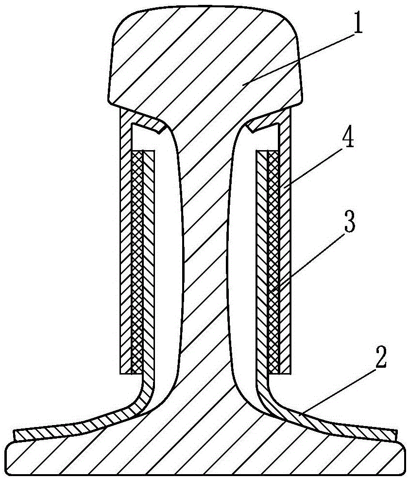
[0029] Such as figure 1 The shearing type track vibration and noise reduction device of the present invention shown in the present invention comprises an upper shearing part 4 and a lower shearing part 2, the upper shearing part 4 is located at the outer side of the lower shearing part 2, and the upper shearing part 4 works tightly The ground is pressed against the rail jaw of the rail 1, the lower shearing part 2 is connected with the rail flange, the shape of the lower shearing part 2 is the same as the surface shape of the rail flange corresponding to the assembly position, and the upper shearing There is a damping layer 3 between the cut pieces 2, and the damping layer 3 connects the upper cut piece 4 and the lower cut piece 2 into one body to form a damping sound insulation board, which covers the rail jaw to the outside of the rail flange part of the rail surface between the ends. Among them, the upper shearing part 4 and the lower shearing part 2 are made of steel plat...

Embodiment 2

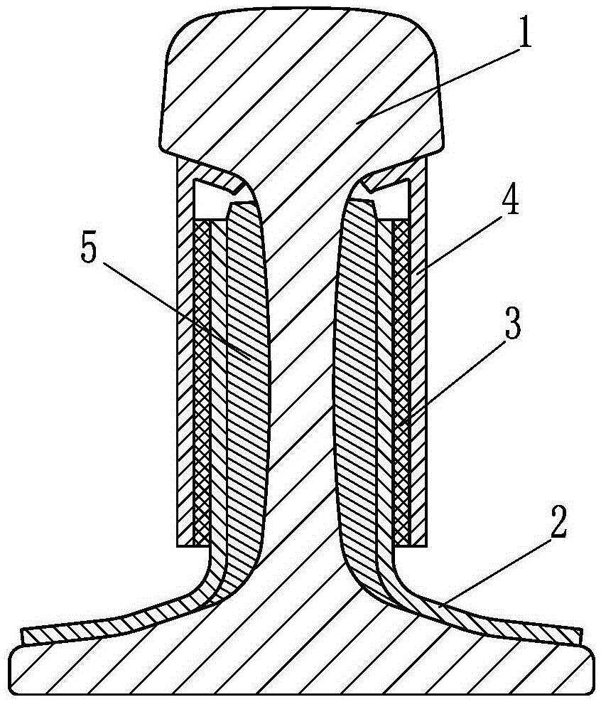
[0034] Such as figure 2 The difference between the shear type rail vibration and noise reduction device of the present invention shown in Embodiment 1 is that, in order to further improve the noise reduction effect, a sound-absorbing material layer 5 is provided between the damping sound insulation board and the rail 1 . Wherein, the sound-absorbing material layer 5 is made of rock wool material.

[0035] The technical solution described in this example, in addition to the various advantages of Embodiment 1, since the sound-absorbing material layer 5 is set between the damping sound-insulating plate and the rail 1, the sound-absorbing material layer 5 basically covers the rail waist of the rail 1 On the surface, when the rail vibrates, the sound-absorbing material layer 5 will absorb the radiation noise of the rail waist, suppress the formation of noise sound waves, and have a stronger ability to block the radiation of rail vibration noise, which improves the performance of t...

Embodiment 3

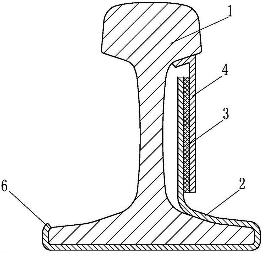
[0038] Such as image 3 The difference between the shearing type rail vibration and noise reduction device of the present invention shown in Embodiment 1 is that the lower shearing part 2 is correspondingly installed on the wing plate and the bottom of the rail 1, and the lower shearing part 2 is provided with a buckle structure6. When assembling with the rail 1, the shearing type rail vibration and noise reduction device of the present invention is fastened together with the rail by using the buckle structure 6 .

[0039] It should be pointed out that when the shear type rail vibration and noise reduction device of the present invention is assembled with the rail, it can be as follows: image 3 The upper shearing part 4 shown is pressed against the rail jaw under the rail head on the right side of the rail, and the buckle structure 6 is fastened to the flange on the left side of the rail. The lower shearing part of the noise reduction device presses against the rail jaw und...


PUM


Abstract

The invention belongs to the field of rail transit damping and noise control and particularly relates to a damping device which is arranged on a non-working surface of a steel rail and is used for reducing vibration and noise generated due to steel rail compressing during a rail vehicle running process. The shearing type track damping noise reducing device comprises an upper shearing piece and a lower shearing piece. The upper shearing piece is in tight contact with or connected with rail sides. At least part of the lower shearing piece is connected with a steel rail wing plate. A damping layer is formed between the upper shearing piece and the lower shearing piece. The upper shearing piece and the lower shearing piece are fixedly connected integrally through the damping layer to form a damping sound barrier plate. The damping sound barrier plate at least covers part of the steel rail surface between the steel rail sides to the outer end of the steel rail wing plate. The shearing type track damping noise reducing device can absorb rail head vibration energy quickly, and meanwhile steel rail radiation noise can be lowered.

Description

technical field [0001] The invention belongs to the field of vibration and noise control of rail traffic, and in particular relates to a vibration damping device arranged on a non-working surface of a rail and used to reduce the vibration and noise generated by the rail during rail vehicle operation. Background technique [0002] In the field of rail transit, free damping or constrained damping treatment of rails, that is, directly laying damping materials on the non-working surface of rails or bonding constrained damping plates, is the main method to control rail vibration and noise. However, on the one hand, the vibration reduction effect of the existing constrained damping structure is proportional to the effective working area of ​​the damping material in the structure, and the available non-working surface of the rail is limited, so the vibration reduction effect of this type of technology is greatly restricted On the other hand, the rail head is in direct contact with ...

Claims


Application Information

Patent Timeline
Patent Type & Authority Patents(China)
IPC IPC(8): E01B19/00
Inventor 尹学军王平孔祥斐颜华王建立姚力王建赵才有刘兴龙高星亮王乾安薛松郭超
Owner QINGDAO CREATE ENVIRONMENT CONTROL TECH
Why Eureka
Try Eureka