a sports slide

A sliding rail and movement technology, applied in the field of manipulators, can solve problems such as shortening the service life of sliding rails, strong vibration, rigid impact of sliding parts, etc., and achieve the effect of improving ride comfort and reducing depth

Active Publication Date: 2017-06-13
宁夏巨能机器人股份有限公司
View PDF1 Cites 0 Cited by
  • Summary
  • Abstract
  • Description
  • Claims
  • Application Information

AI Technical Summary

Problems solved by technology

However, this structure will bring strong vibration when locking, especially for heavy-duty working conditions, this vibration will cause serious rigid impact on sliding parts, greatly shortening the service life of the slide rail

Method used


Image

  • a sports slide
  • a sports slide

Examples


Embodiment 1

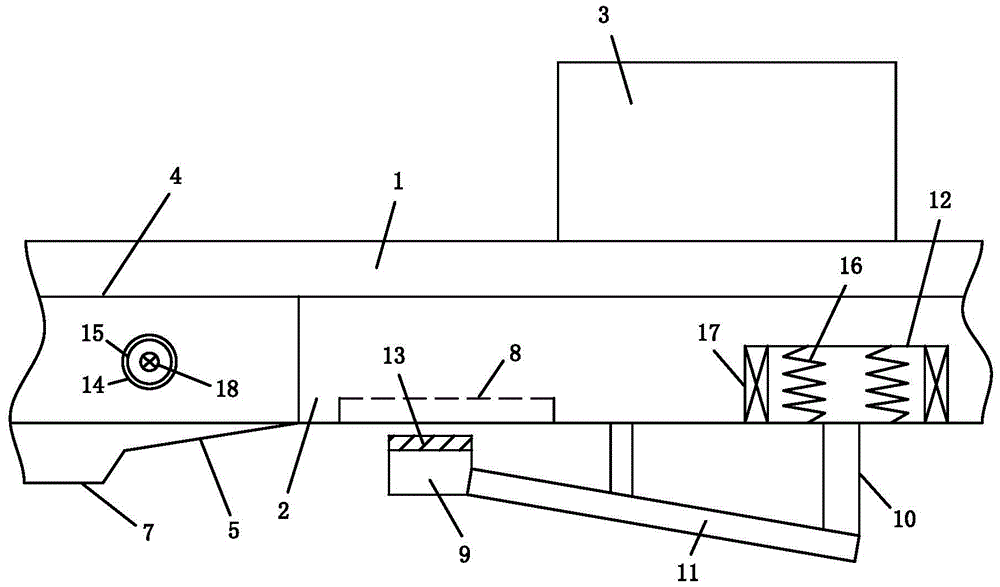
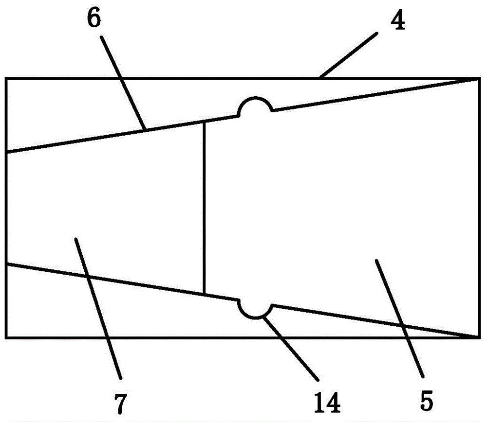
[0015] Reference Figure 1-2 , This embodiment includes a first slide rail 1 and a second slide rail 2 slidingly sleeved in the first slide rail 1. The first slide rail 1 and the second slide rail 2 are connected by ball bearings. The installation angle of the ball bearing An angle of 10° with the horizontal. A load-bearing mechanism 3 is connected above the second slide rail 2. At least one positioning portion 4 is provided in the first slide rail 1. The bottom surface of the positioning portion 4 is provided with a downwardly inclined first inclined surface 5, and a side of the positioning portion 4 The wall is symmetrically provided with a second inclined surface 6 inclined to the inside. The end of the first inclined surface 5 is connected with a fixing groove 7; the front end of the second slide rail 2 is provided with an elongated through hole 8, below the elongated through hole 8 A damping sheet 9 and a top block 10 are provided. The damping sheet 9 and the top block 10...

Embodiment 2

[0021] This embodiment is an improvement made on the basis of Embodiment 1, and the same parts as Embodiment 1 will not be described in detail. Among them, the damping sheet 9 is made by mixing silica gel and graphite according to a ratio of 9.5:1, wherein the particle diameter of graphite is preferably 10 μm-30 μm, the pattern layer 13 is a uniform diamond pattern, and the width of the convex side of the diamond pattern is two The ratio of the lengths of the diagonals is 1:15:23. This preferred solution can realize low-noise and fast locking and positioning.

Embodiment 3

[0023] This embodiment is an improvement made on the basis of Embodiment 1, and the same parts as Embodiment 1 will not be described in detail. Among them, the damping sheet 9 is mixed with styrene-butadiene rubber and graphite according to a ratio of 13:1, wherein the particle diameter of graphite is preferably 3 μm to 5 μm, the pattern layer 13 has 5 parallel stripes, and the ratio of the width of the stripes is 1:3: 4:3:1. This preferred solution can prolong the service life of the damper.

[0024] The working principle of the present invention is that the present invention utilizes the first inclined surface 5 in the positioning portion 4 to buffer the positioning process during positioning and avoid vibration caused by sudden locking positioning. The second inclined surface 6 is used to generate a buffing force on the second slide rail 2, on the one hand, it has a decelerating effect, and on the other hand, it can suppress the lateral vibration generated by the second slide...


PUM


Abstract

The invention discloses a moving slide rail, which comprises a first slide rail and a second slide rail slidingly sleeved in the first slide rail, a load-bearing mechanism is connected above the second slide rail, and a At least one positioning part, the bottom surface of the positioning part is provided with a first inclined surface inclined downward, the side wall of the positioning part is symmetrically provided with a second inclined surface inclined inwardly, and the end of the first inclined surface is connected with a fixing groove; The front end is provided with a long strip-shaped through hole, and the bottom of the long strip-shaped through hole is provided with a damping sheet and a top block. The damping sheet and the top block are connected with a connecting rod. There is an elastic compression mechanism, and the top block slides and fits with the elastic compression mechanism. The invention can improve the deficiencies of the prior art, and reduces the vibration when the slide rail is locked.

Description

Technical field [0001] The invention relates to the technical field of manipulators, in particular to a moving slide rail. Background technique [0002] In various material transportation places, various slide rails are widely used. Chinese invention patent CN101190075B discloses a slide rail device, which facilitates the locking and unlocking operations of the slide rail. However, this structure will bring strong vibration when locking, especially for heavy load conditions. This vibration will cause severe rigid impact on the sliding parts, greatly shortening the service life of the sliding rail. Summary of the invention [0003] The technical problem to be solved by the present invention is to provide a moving slide rail, which can solve the shortcomings of the prior art and reduce the vibration when the slide rail is locked. [0004] To solve the above technical problems, the technical solutions adopted by the present invention are as follows. [0005] A moving slide rail includ...

Claims


Application Information

Patent Timeline
Patent Type & Authority Patents(China)
IPC IPC(8): B65G35/00
Inventor 宋明安王小龙孙洁同彦恒李志博麻辉
Owner 宁夏巨能机器人股份有限公司
Why Eureka
Try Eureka