Eureka AIR delivers breakthrough ideas for toughest innovation challenges, trusted by R&D personnel around the world.

Camera fixing support for crash test

A camera fixation and collision test technology, which is applied to the camera, the camera body, the supporting machine, etc., can solve the problems that the camera cannot be effectively fixed, and achieve the effect of simple structure.

Active Publication Date: 2014-08-27
ZHEJIANG GEELY HOLDING (GROUP) CO LTD +1
View PDF6 Cites 1 Cited by
  • Summary
  • Abstract
  • Description
  • Claims
  • Application Information

AI Technical Summary

Problems solved by technology

[0004] The existing camera fixing method is usually to fix the camera on the windshield glass and engine compartment cover of the test vehicle, and the dummy set in the car includes the front seat dummy set on the front seat and the rear seat dummy set on the rear seat. For the dummy, the camera fixed in the above way can only be used to shoot the position movement of the dummy in the front seat, while the camera for the dummy in the rear seat cannot be effectively fixed, so an additional fixing bracket can only be installed on the car body so that the camera can pass through the dummy. The fixing bracket is installed on a specific position of the car body (such as the door), but there is no fixing bracket with a simple structure and convenient for fixing the camera for shooting the dummy in the rear seat

Method used


Image

  • Camera fixing support for crash test
  • Camera fixing support for crash test
  • Camera fixing support for crash test

Examples


Embodiment Construction

[0021] In order to describe the technical content, structural features, achieved goals and effects of the present invention in detail, the following will be described in detail in conjunction with the embodiments and accompanying drawings.

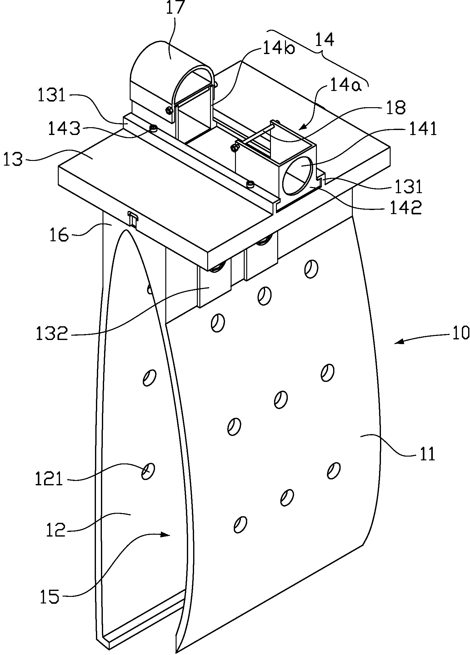
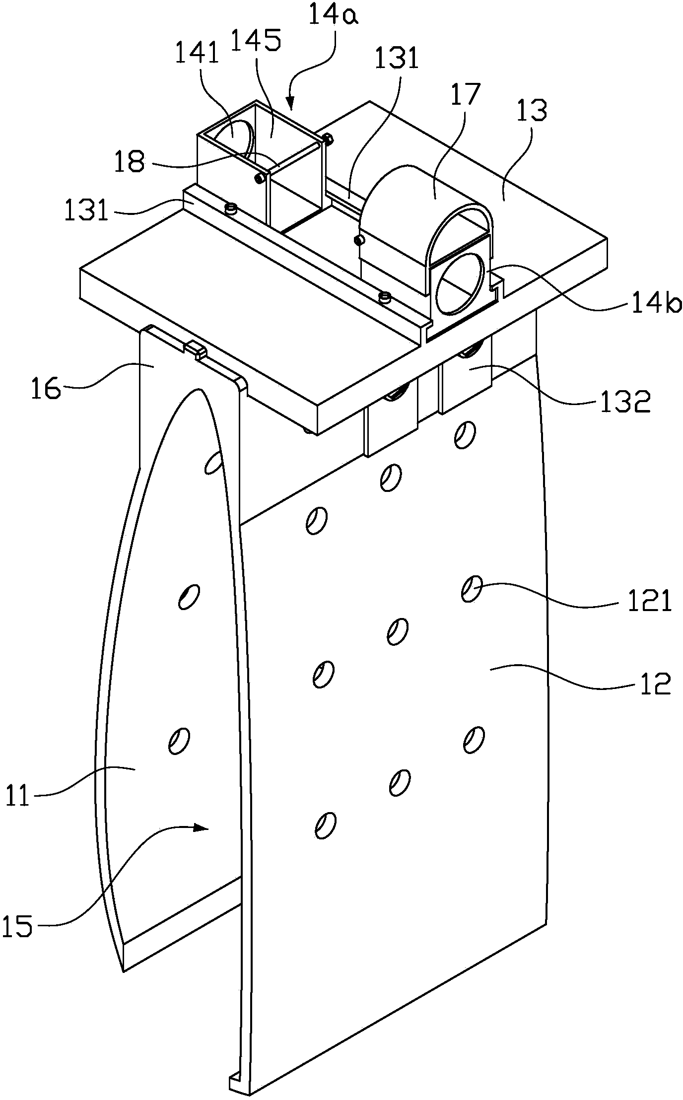
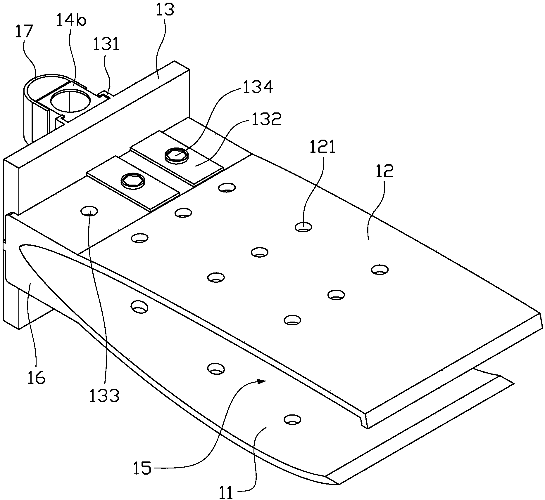
[0022] Please refer to Figure 1 to Figure 4 , the camera fixing bracket of the embodiment of the present invention is used to fix the camera 20 on the car door 30 during the automobile crash test, so that the camera 20 can perform the positional movement of the dummy in the car (the dummy in the front seat or the dummy in the back seat) shoot. The camera fixing bracket 10 includes a fixing board 11 , a fixing side board 12 , and a supporting board 13 . Wherein, the fixed board 11 and the fixed side board 12 are mutually spaced and oppositely arranged, and a draw-in groove 15 is formed between the fixed board 11 and the fixed side board 12, and the top of the fixed board 11 is connected to the top of the fixed side board 12 to form a conn...


PUM


Abstract

Provided is a camera fixing support for a crash test. The camera fixing support is used for fixing a camera on a vehicle door during the vehicle crash test. The vehicle door comprises an inner side part and an outer side part in the horizontal direction of a vehicle. A slot for containing vehicle door glass is formed between the inner side part and the outer side part. The camera fixing support comprises a fixing inserting plate, a fixing side plate and a supporting plate. The fixing inserting plate and the fixing side plate are arranged at intervals oppositely. A clamping groove is formed between the fixing inserting plate and the fixing side plate. The top end of the fixing inserting plate and the top end of the fixing side plate are connected with each other to form a connecting part. The supporting plate is fixed on the connecting part. The camera is fixed on the supporting plate. The fixing inserting plate is inserted into the slot. The fixing side plate is placed on one side outside the vehicle. The outer side part of the vehicle door is clamped in the clamping groove. The fixing side plate is fixed on the outer side part of the vehicle door through a fastening piece. The camera fixing support is simple in structure, and the camera for shooting a dummy can be conveniently fixed at the position of a left vehicle door or a right vehicle door.

Description

technical field [0001] The invention relates to the technical field of automobiles, in particular to a camera fixing bracket for fixing a shooting camera on a vehicle body during an automobile collision test. Background technique [0002] With the rapid development of the automobile industry, traffic safety is a common issue faced by all countries in the world. Strengthening research on automobile safety and reducing road traffic injuries in our country is one of the important social issues that the whole society pays close attention to and strives to solve. [0003] The research on automobile safety is mainly realized through automobile crash tests. According to different automobile models, the requirements and parameters of each test are also different. At the same time of the test, the requirements for high-speed photography are very high, because at the moment of the collision, the position movement of the test dummy is observed according to the speed of the camera at 10...

Claims


Application Information

Patent Timeline
Patent Type & Authority Applications(China)
IPC IPC(8): G03B17/56F16M13/02
Inventor 栾朋杨君王章平魏亚明韩刚刘卫国潘之杰吴成明冯擎峰
Owner ZHEJIANG GEELY HOLDING (GROUP) CO LTD
Why Eureka
Eureka Blog
Learn More