
Wire coiling device for reducer

A winding device and speed reducer technology, which is applied in the direction of electromechanical devices, coil manufacturing, and motor generator manufacturing, can solve the problems of increasing the difficulty and efficiency of installation, affecting the use effect and installation efficiency of the reducer, and loose coils, etc., to achieve The structure is simple, the design is reasonable, and the coil is stable and firm.

Inactive Publication Date: 2014-08-27
含山县众力铸造有限公司
View PDF3 Cites 0 Cited by
  • Summary
  • Abstract
  • Description
  • Claims
  • Application Information

AI Technical Summary

Problems solved by technology

[0003] In order to improve the deceleration effect of the reducer, it is often necessary to install different coils, and installing different high and low voltage coils will increase the difficulty and efficiency of installation, and also increase the production process, and this separate coil installation often occurs The phenomenon of loose coils will directly affect the use effect and installation efficiency of the reducer

Method used


Image

  • Wire coiling device for reducer

Examples


Embodiment Construction

[0013] In order to make the technical means, creative features, goals and effects achieved by the present invention easy to understand, the present invention will be further described below in conjunction with specific illustrations.

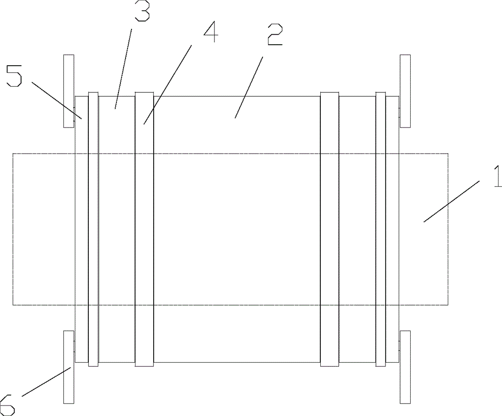
[0014] Such as figure 1 As shown, a winding device for a reducer includes an amorphous iron core 1, a high-voltage coil 2, a low-voltage coil 3 and an insulator 4. The high-voltage coil 2 is wound and installed in the middle of the amorphous iron core 1, and the high-voltage wire The two ends of the coil 2 are fitted with insulating parts 4, and the insulating parts 4 are in a ring-shaped structure. The low-voltage coils 3 are installed on the outer sides of the two ends of the insulating parts 4, and at the same time, the outer parts of the low-voltage coils 3 at both ends are continuously matted. Insulators 4, and end plates 5 are respectively installed on the outer ends of the outermost insulators 4 at both ends, and the end plates 5 are also...


PUM


Abstract

The invention discloses a wire coiling device for a reducer and relates to the technical field of reducer manufacturing. The wire coiling device for the reducer comprises an amorphous iron core, a high-tension coil, low-tension coils and insulating pieces. The high-tension coil is installed in the middle of the amorphous iron core in a winding mode, and the insulating pieces are installed at the two ends of the high-tension coil in a cushioned mode. The insulating pieces are of circular-ring-shaped structures. The outer sides of the two ends of the insulating pieces are provided with the low-tension coils, and the outer sides of the low-tension coils at the two ends of the insulating pieces are continuously provided with the insulating pieces in a cushioned mode. The outer ends of the insulating pieces of the outermost sides of the two ends are further provided with end plates respectively, and the end plates are of circular-ring-shaped structures. The end plates and the insulating pieces share the same diameter, and the outer sides of the two ends of the end plates are provided with clamping devices respectively. The clamping devices are fixedly connected through bolts. The wire coiling device is simple in structure, reasonable in design and convenient to use; the coils are stable and firm, the high-tension coil and the low-tension coils can be arranged in the same time in a winding mode and cannot loosen, and the installation efficiency of a motor can be improved.

Description

Technical field: [0001] The invention relates to the technical field of reducer manufacturing, in particular to a winding device for a reducer. Background technique: [0002] The speed reducer plays the role of matching speed and transmitting torque between the prime mover and the working machine or the actuator. The speed reducer is a relatively precise machine. The purpose of using it is to reduce the speed. The independent components composed of gear transmission, worm transmission, and gear-worm transmission in the body are often used as a reduction transmission device between the prime mover and the working machine to match the speed and transmit torque between the prime mover and the working machine or the actuator. It is widely used in modern machinery. [0003] In order to improve the deceleration effect of the reducer, it is often necessary to install different coils, and installing different high and low voltage coils will increase the difficulty and efficiency of...

Claims


Application Information

Patent Timeline
IPC IPC(8): H02K15/08H01F41/06H01F41/09
Inventor 张涛
Owner 含山县众力铸造有限公司
Learn More