A compound structure double-winding bearingless switched reluctance motor

A switched reluctance motor, reluctance motor technology, applied in the shape/style/structure of winding conductors, electrical components, electromechanical devices, etc., can solve the problems of large demand for enameled wires, limited application scope, low winding utilization, etc. The effect of convenient control, strong high-speed adaptability and large radial suspension force

Active Publication Date: 2016-02-10
NANJING UNIV OF POSTS & TELECOMM
View PDF9 Cites 0 Cited by
  • Summary
  • Abstract
  • Description
  • Claims
  • Application Information

AI Technical Summary

Problems solved by technology

The suspension winding enameled wire has a large demand, consumes copper, and the winding utilization is low; in addition, the motor can only be used as a generator, which limits its application range

Method used


Image

  • A compound structure double-winding bearingless switched reluctance motor
  • A compound structure double-winding bearingless switched reluctance motor
  • A compound structure double-winding bearingless switched reluctance motor

Examples


Embodiment Construction

[0028] The technical scheme of a composite structure double-winding bearingless switched reluctance motor of the present invention will be described in detail below in conjunction with the accompanying drawings:

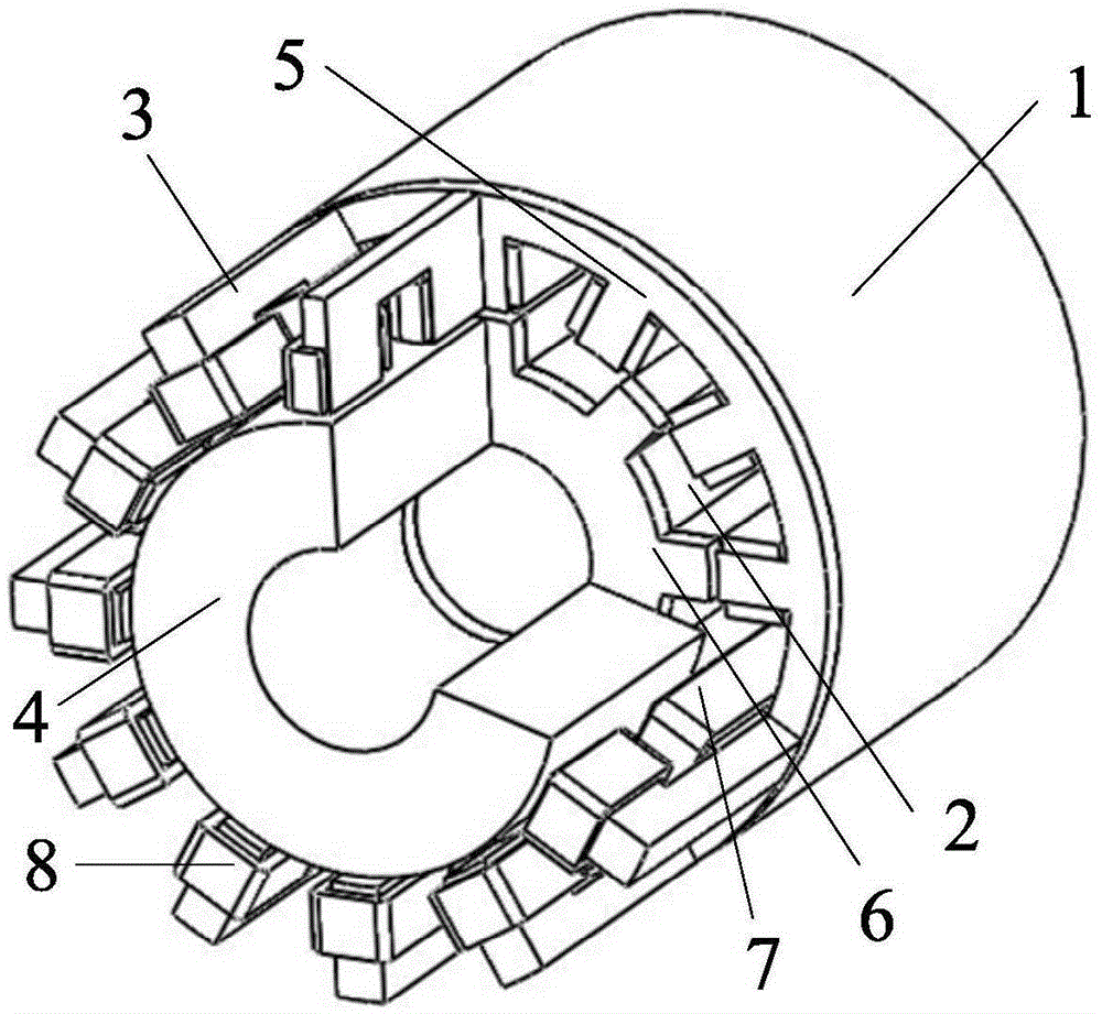
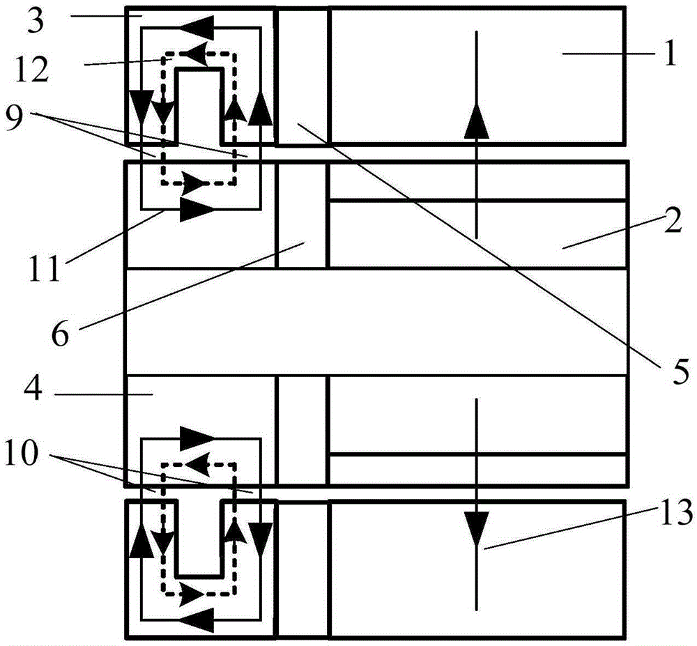
[0029] Such as figure 1 As shown, a three-dimensional structural schematic diagram of a composite structure double-winding bearingless switched reluctance motor of the present invention, wherein, 1 is the stator core of the reluctance motor, 2 is the rotor core of the reluctance motor, 3 is the stator core of the magnetic bearing, and 4 is The magnetic bearing rotor core, 5 is the spacer stator, 6 is the spacer rotor, 7 is the torque winding, and 8 is the suspension force winding.

[0030] The motor stator is composed of a reluctance motor stator, a spacer stator and a magnetic bearing stator through axial superposition, wherein the spacer stator is arranged between the reluctance motor stator and the magnetic bearing stator; the reluctance motor stator and the magne...


PUM


Abstract

The invention discloses a duplex-winding bearing-free switched reluctance motor of a composite structure. The motor comprises a motor stator, a motor rotor and motor windings. The motor stator is composed of a reluctance motor stator, a magnetic separation disc stator and a magnetic bearing stator. The motor rotor is composed of a reluctance motor rotor, a magnetic separation disc rotor and a magnetic bearing rotor. The magnetic bearing stator is of a [-shaped structure, and the magnetic bearing rotor is of a cylindrical structure. The reluctance motor stator and the reluctance motor rotor are both of a salient pole structure. The motor windings comprise the torque winding and the suspension force winding. The torque winding is wound on one tooth of a [-shaped iron core of the reluctance motor stator, one tooth of a [-shaped iron core of the magnetic separation disc stator and one tooth of a [-shaped iron core of the magnetic bearing stator. The suspension force winding is wound on the other tooth of the [-shaped iron core of the magnetic bearing stator. According to the duplex-winding bearing-free switched reluctance motor of the composite structure, the reluctance motor rotor generates torque, suspension force rotors generate suspension force, and decoupling of the torque and the suspension force is achieved structurally; motional electromotive force is zero in a suspension breakover interval, influences of the motional electromotive force on current chopped waves are eliminated, and the current real-time control effect is improved.

Description

technical field [0001] The invention belongs to the technical field of motors, and relates to a double-winding bearingless switched reluctance motor with a composite structure. Background technique [0002] The bearingless switched reluctance motor is a new type of magnetic levitation motor developed at the end of the 20th century. According to the number of windings wound on the stator, it can be divided into single winding and double winding structures. Composite structure double-winding bearingless switched reluctance motor is to stack the levitation winding which generates the levitation force and the winding of the original switched reluctance motor on the stator of the motor. By controlling the current of the two sets of windings, it has the ability to rotate and self-levitate at the same time. , so as to realize the ultra-high-speed operation of the motor. [0003] There is a strong coupling relationship between the torque and the levitation force of the composite s...

Claims


Application Information

Patent Timeline
Patent Type & Authority Patents(China)
IPC IPC(8): H02K16/00H02N15/00H02K3/28
Inventor 刘泽远杨艳曹鑫邓智泉王世山
Owner NANJING UNIV OF POSTS & TELECOMM
Why Eureka
Try Eureka