The locking structure of the sliding sleeve of the main shaft of the centering machine and the claw

A technology of locking structure and walking machine, which is applied in the directions of metal processing machinery parts, clamping, and support, can solve the problems of easy deformation and low rigidity of the ejector rod, and achieve the effect of increasing rigidity, solving easy deformation and improving rigidity.

Active Publication Date: 2016-11-30
NANJING JIANKE MACHINERY
View PDF6 Cites 1 Cited by
  • Summary
  • Abstract
  • Description
  • Claims
  • Application Information

AI Technical Summary

Problems solved by technology

[0003] The purpose of the present invention is to provide a locking structure in which the sliding sleeve of the main shaft of the centering machine cooperates with the claws, so as to solve the technical defects of the lower rigidity and easy deformation of the ejector rod in the prior art

Method used


Image

  • The locking structure of the sliding sleeve of the main shaft of the centering machine and the claw
  • The locking structure of the sliding sleeve of the main shaft of the centering machine and the claw
  • The locking structure of the sliding sleeve of the main shaft of the centering machine and the claw

Examples


Embodiment Construction

[0019] The specific embodiments of the present invention will be further described below in conjunction with the drawings.

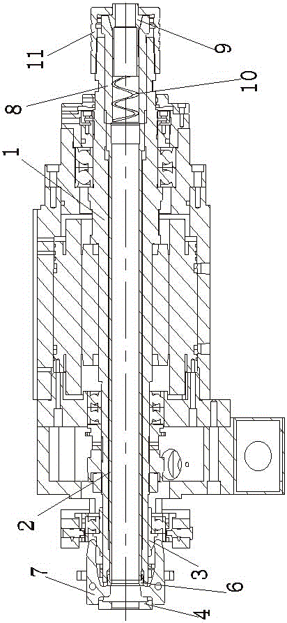
[0020] Such as figure 1 The shown locking structure of the sliding sleeve of the main shaft of the walking machine with the jaws includes a main shaft 1 with a first central hole penetrating both ends of the main shaft 1 along the axial direction; A movable mandrel 2; a jacket 8 that is arranged in the front end of the first central hole of the main shaft 1 and can be pushed by the mandrel 2 to move axially. The jacket 8 has a second central hole penetrating both ends of the jacket 8 in the axial direction. The front end of the center hole is provided with a chuck 9 (standard part, available in the market according to the required model) and the front end of the second center hole is a horn with a large front end and a small rear end that matches the chuck 9 The rear end of the second central hole is provided with a compression spring 10, the diameter of th...


PUM


Abstract

The invention discloses a locking structure in which a sliding sleeve of a main shaft of a centering machine cooperates with a claw, comprising a main shaft; an ejector rod arranged in the rear end of the first central hole of the main shaft; , the jacket has a second central hole along the axial direction, a collet is arranged at the front end of the second central hole, and a pressure spring is arranged at the rear end of the second central hole; a jacket nut is arranged at the front end of the main shaft; a sliding sleeve is set at the rear end of the main shaft ;Symmetric claw seat with upper and lower two through grooves; front end is set on the push ring at the end of the ejector rod; "L" shaped claw, the front and rear ends of the claw are respectively free end and transmission end, the claw The rotation is arranged in the through groove, the free end is attached to the outer surface of the sliding sleeve, and the transmission end is located at the rear end of the push ring to push the push ring to move axially. The beneficial effects of the invention are: the whole structure has better rigidity and is not easily deformed, and the invention also has the advantage of simple structure.

Description

Technical field [0001] The invention relates to the field of mechanical accessories, in particular to a locking structure of a sliding sleeve of a main shaft of a walking machine with a jaw. Background technique [0002] At present, pneumatic clamping is generally adopted in the core walking machines on the market. The sliding sleeve is driven by the cylinder, and the material is clamped by the cooperation of the jaw and the sliding sleeve. The end of the spindle is fitted with a jaw seat, and the jaw is rotated and set on the jaw. On the seat, the ejector rod is simultaneously grooved in the axial direction, the free end of the jaw moves on the sliding sleeve, and the transmission end of the jaw moves along the axial direction of the ejector rod in the groove on the ejector rod. It is easy to control and difficult to process, which causes inconvenience to assembly, debugging and maintenance. In addition, the processed ejector rod and spindle will affect its overall rigidity, the...

Claims


Application Information

Patent Timeline
Patent Type & Authority Patents(China)
IPC IPC(8): B23Q3/12B23B19/02
Inventor 王建飞
Owner NANJING JIANKE MACHINERY
Why Eureka
Try Eureka