
A fixture positioning and clamping device

A clamping device and inspection tool technology, which is applied to workpiece clamping devices, manufacturing tools, etc., can solve the problems of squatting, affecting the authenticity and accuracy of precision detection, and poor positioning stability of parts to be inspected. The effect of improving accuracy and ensuring stability

Active Publication Date: 2016-06-01
ANHUI JIANGHUAI AUTOMOBILE GRP CORP LTD
View PDF10 Cites 0 Cited by
  • Summary
  • Abstract
  • Description
  • Claims
  • Application Information

AI Technical Summary

Problems solved by technology

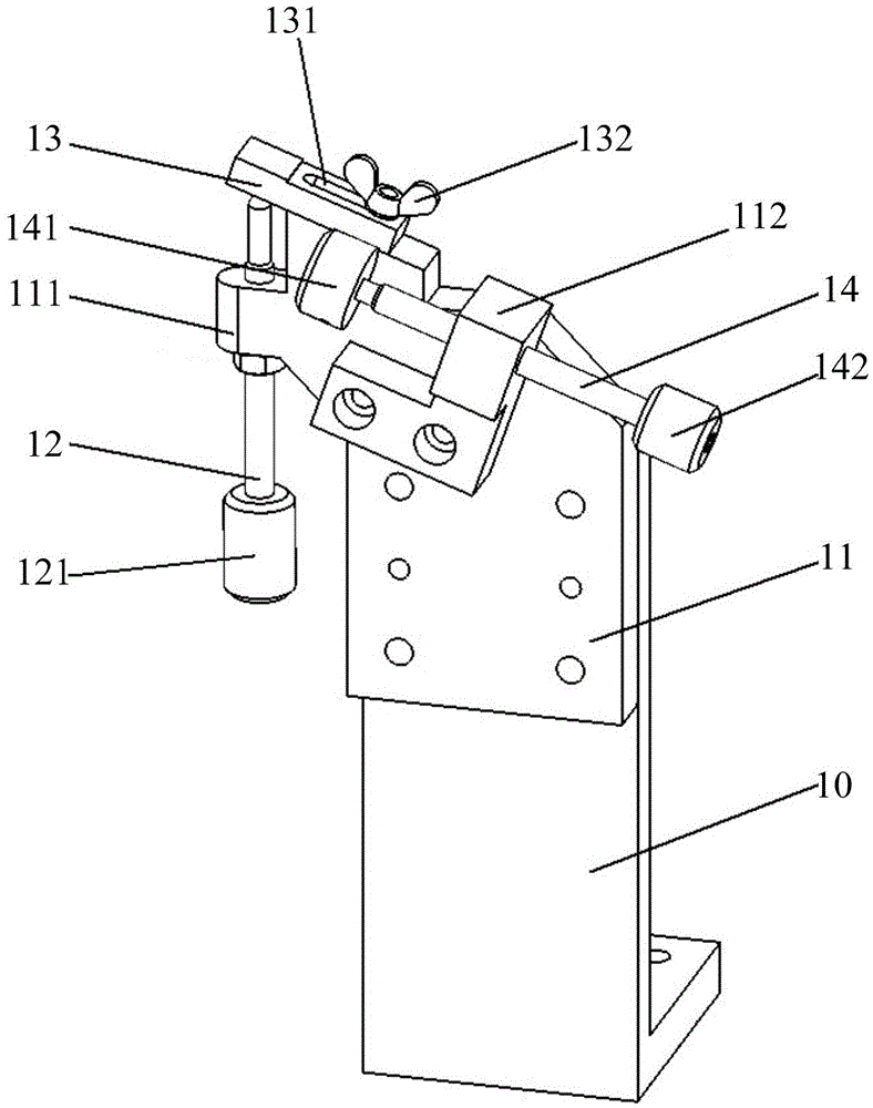
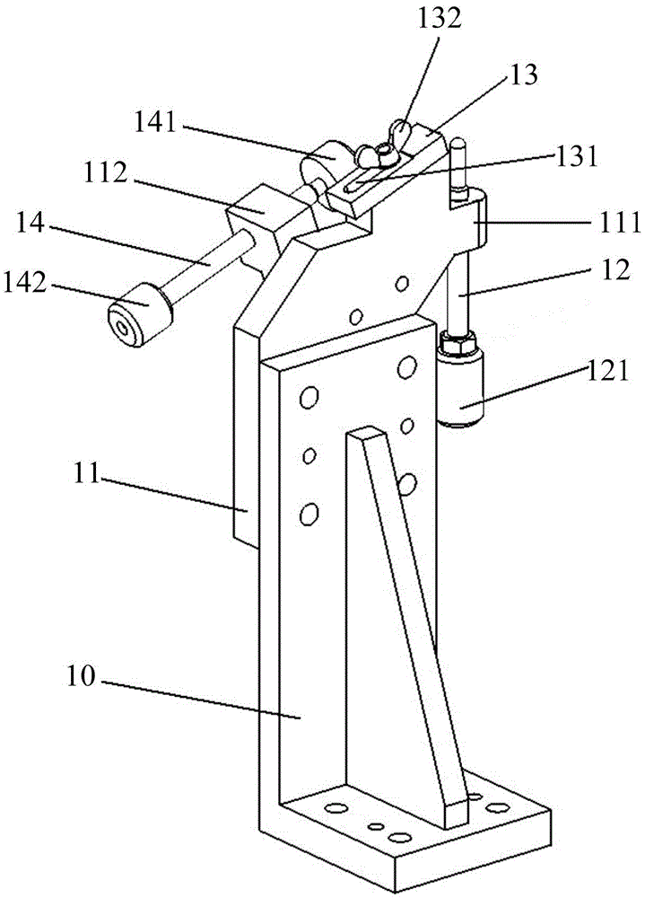
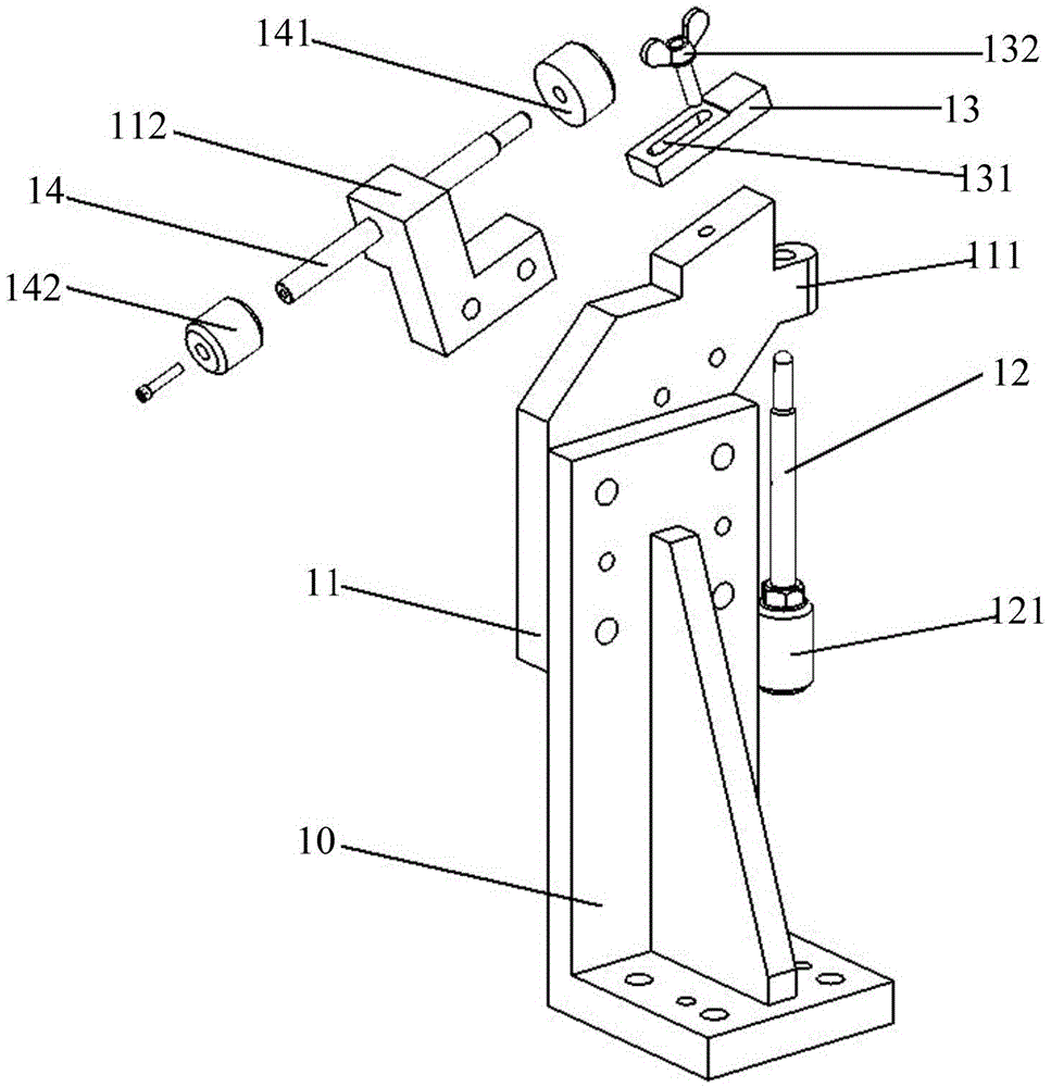
For parts to be inspected that are placed vertically in space, the existing positioning and clamping devices can only achieve clamping and positioning in a single coordinate direction, and the positioning stability of the parts to be inspected is not good, and often occurs during the inspection process due to the existence of its own gravity. Accumulation, thereby affecting the authenticity and accuracy of precision detection

Method used


Image

  • A fixture positioning and clamping device
  • A fixture positioning and clamping device
  • A fixture positioning and clamping device

Examples


Embodiment Construction

[0018] In order to make the above objects, features and advantages of the present invention more comprehensible, specific implementations of the present invention will be described in detail below in conjunction with the accompanying drawings.

[0019] In the following description, many specific details are set forth in order to fully understand the present invention, but the present invention can also be implemented in other ways than those described here, so the present invention is not limited by the specific embodiments disclosed below.

[0020] Secondly, the present invention is described in detail in conjunction with schematic diagrams. When describing the embodiments of the present invention in detail, for the convenience of explanation, the sectional view showing the structure of the device will not be partially enlarged according to the general scale, and the schematic diagram is only an example, and it should not be limited here. The protection scope of the present in...


PUM


Abstract

The invention discloses a gauge positioning and clamping device. The gauge positioning and clamping device comprises an installing plate provided with a first connecting block, a first ejector rod is installed on the first connecting block through a thread in a matched mode in the first direction, the installing plate is movably connected with a pressing plate, and the first ejector rod and the pressing plate are matched in the first direction to clamp and position a component to be inspected. The surface of the installing plate is connected with a second connecting block, a second ejector rod is installed on the second connecting block through a thread in a matched mode in the second direction, and the second ejector rod positions the component to be inspected in the second direction. According to the gauge positioning and clamping device, the component to be inspected can be positioned in the first direction and the second direction, the situation that the component moves due to gravity of the component to be inspected in the inspection process can be avoided, and therefore the positioning stability of the component to be inspected in the inspection process is ensured.

Description

technical field [0001] The present application relates to the technical field of inspection tools, in particular to a positioning and clamping device for inspection tools. Background technique [0002] In the welding and manufacturing process of automobile bodies, the accuracy of the body-in-white is the main indicator of the welding process level. High-precision body-in-white can not only improve the assembly of assembly parts, but also improve the quality of the body's appearance gap. At present, in the development process of the whole vehicle, most of the stamping parts and welding assemblies of automobiles are inspected and accepted by inspection tools to confirm whether the precision of the stamping parts hole and the contour of the surface are qualified, so as to meet the loading requirements. [0003] However, some parts to be inspected are not placed horizontally for inspection, but are fixed and inspected according to the position of the parts to be inspected in the...

Claims


Application Information

Patent Timeline
Patent Type & Authority Patents(China)
IPC IPC(8): B25B11/00
CPCB25B11/00
Inventor 陈世涛王海玲何鹏申黄涛李辉阮林凡
Owner ANHUI JIANGHUAI AUTOMOBILE GRP CORP LTD
Learn More