Lifting board device of drying machine

A lifting plate and drying machine technology, which is applied in the direction of drying, drying solid materials, lighting and heating equipment, etc., can solve the problem of affecting the normal operation and use effect of the equipment, short continuous operation time of the equipment, and adhesion of the secondary lifting device and other problems, to achieve the effect of reducing thermal voids, reducing production costs and maintenance costs, and reducing equipment weight

Inactive Publication Date: 2014-09-03
SHANDONG ZHANGQIU BLOWER
View PDF6 Cites 1 Cited by
  • Summary
  • Abstract
  • Description
  • Claims
  • Application Information

AI Technical Summary

Problems solved by technology

However, the above-mentioned traditional structure is prone to the following problems in the actual use process: when the moisture content of the material is too high, it is easy to stick or even agglomerate with the secondary lifting device, which affects the overall discharge; with the friction with the material, the "secondary lifting device" It is easy to separate or fall off from the cylinder or support frame, thus affecting the normal operation and use effect of the equipment; the continuous operation time of the equipment is short, and the maintenance cost is too high

Method used


Image

  • Lifting board device of drying machine
  • Lifting board device of drying machine
  • Lifting board device of drying machine

Examples


Embodiment Construction

[0019] In order to clearly illustrate the technical characteristics of this solution, the following describes this solution through a specific implementation and in conjunction with the accompanying drawings.

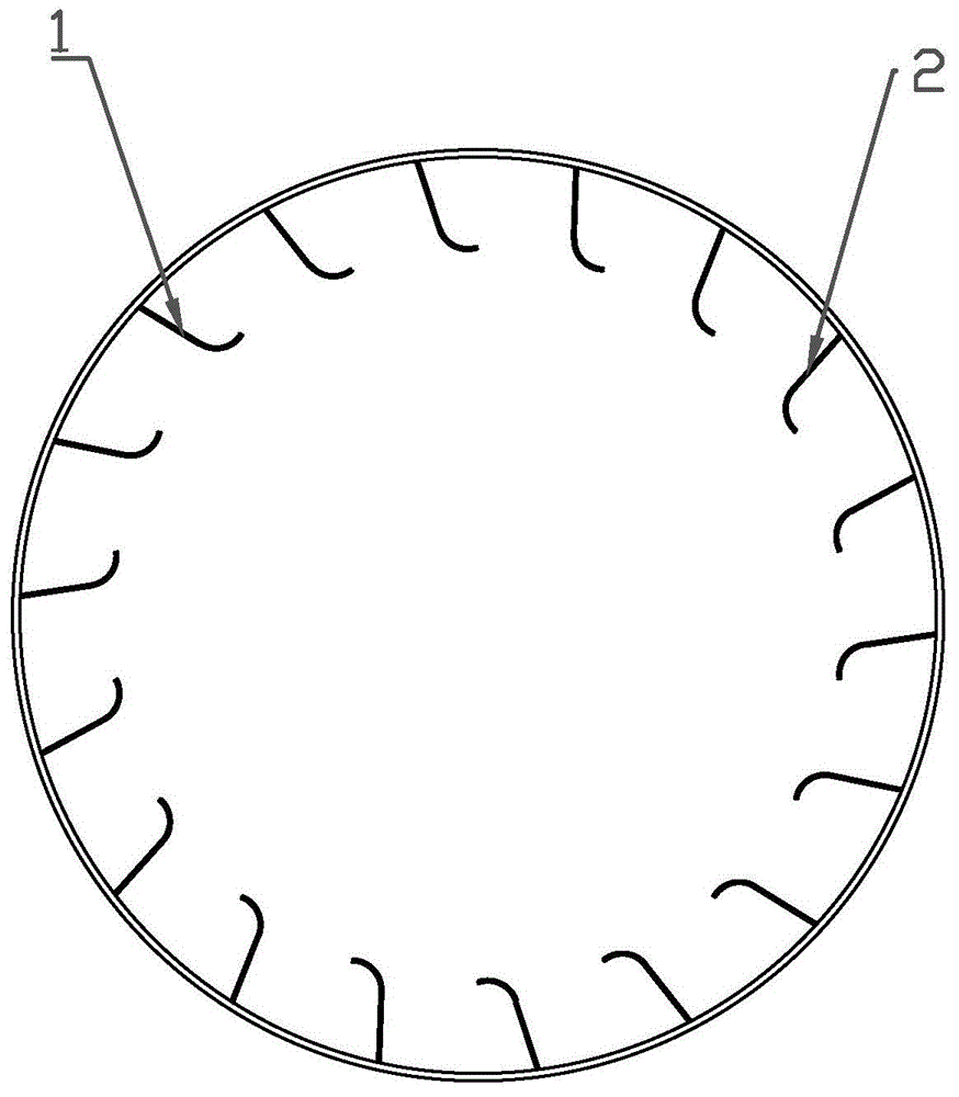
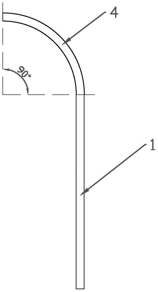
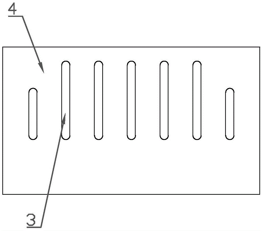
[0020] Such as Figure 1-4 As shown, a lifting plate device of a dryer of the present invention includes a lifting plate 1 and a drying cylinder 2 on which the lifting plate 1 is installed. The lifting plate 1 is arranged inside the drying cylinder 2 There are a plurality of said lifting plates 1 which are evenly distributed inside the drying cylinder 2. Said lifting plates 1 are steel lifting plates, and the upper end of the lifting plates 1 is curved in an arc shape. The bending angle of the bending part of the lifting plate 1 is 90°.

[0021] The connection between the lifting plate 1 and the drying cylinder 2 can be welded or screwed according to the actual situation. The lifting plate 1 can be installed on the drying cylinder 2. Ensure that the lifting plate 1 has the...


PUM

PropertyMeasurementUnit
Bending angleaaaaaaaaaa
Lengthaaaaaaaaaa
Widthaaaaaaaaaa

Abstract

The invention discloses a lifting board device of a drying machine. The lifting board device comprises a plurality of lifting boards and a drying barrel body for installing the lifting boards, wherein the lifting boards are uniformly arranged in the drying barrel body and are welded on the drying barrel body. The lifting board device is characterized in that seven or eight grid gaps are formed in each lifting board; the upper end of each lifting board is bent and is in an arc shape; the grid gaps are distributed in the arc-shaped part of each lifting board; the length of each grid gap is 120-180 mm and the width of each grid gap is 10-15 mm; the lifting boards comprise forward lifting boards, backward lifting boards and horizontal lifting boards which are distributed in a staggered manner in the drying barrel body. The lifting board device of the drying machine has the characteristics of small size, light weight, simple structure and convenience in installing and maintenance, and the technical problem in a traditional inner structure of a drying machine is effectively solved.

Description

Technical field [0001] The invention relates to an internal fitting of a tumble dryer, in particular to a lifting plate device of a dryer. Background technique [0002] At present, the dryers used in the domestic building materials industry mostly adopt the traditional structure of the combination of the main lifting plate and the secondary lifting device inside the cylinder. The main lifting plate is the ordinary lifting plate, which is directly connected to the inner wall of the cylinder and rotates with the cylinder. Its function is to pick up the material from the bottom of the cylinder and throw it down at a certain height; the secondary lifting device is supported by The frame is fixed to the central part of the cylinder. In this way, by adding a steel structure inside the cylinder, the falling of the material can be delayed, thereby increasing the contact time and contact area of ​​the hot air with the material, and achieving the purpose of improving the moisture evaporat...

Claims


Application Information

Patent Timeline
IPC IPC(8): F26B25/04
Inventor 马广海梅启明李司春
Owner SHANDONG ZHANGQIU BLOWER
Why Eureka
Try Eureka