Dryer material lifting mechanism

A dryer and lifting plate technology, which is applied to drying, drying solid materials, lighting and heating equipment, etc., can solve the problems affecting the normal operation and use effect of the equipment, the continuous operation time of the equipment is short, and the maintenance cost is high. The effect of increased contact time, increased contact area, and increased drying output

Inactive Publication Date: 2018-11-16
李晓
View PDF0 Cites 2 Cited by
  • Summary
  • Abstract
  • Description
  • Claims
  • Application Information

AI Technical Summary

Problems solved by technology

However, the above-mentioned structure is prone to the following problems in the actual use process: when the moisture content of the material is too high, it is not easy to dry, which wastes resources; with the friction with the material, the lifting plate is easily broken by the material, thus affecting the normal operation and operation of the equipment. The effect of use; the continuous operation time of the equipment is short, and the maintenance cost is too high

Method used


Image

  • Dryer material lifting mechanism
  • Dryer material lifting mechanism

Examples


Embodiment Construction

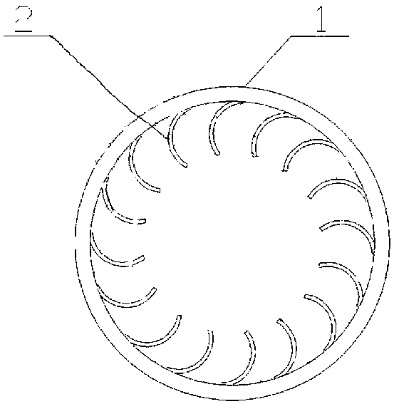
[0021] Such as Figure 1-2 As shown, a dryer lifting mechanism includes 24 sets of lifting assemblies 2 arranged at equal intervals along the axial direction of the drum 1, and each group of lifting assemblies 2 includes eight 8 sets of lifting assemblies arranged at equal intervals along the axial direction of the rotating drum 1. One lifting plate, the lifting plates of the adjacent lifting components 2 are arranged alternately, the angle between the connection point between the adjacent lifting plates of the adjacent lifting components 2 and the inner wall of the drum 1 and the axis of the drum 1 is 22.5°.

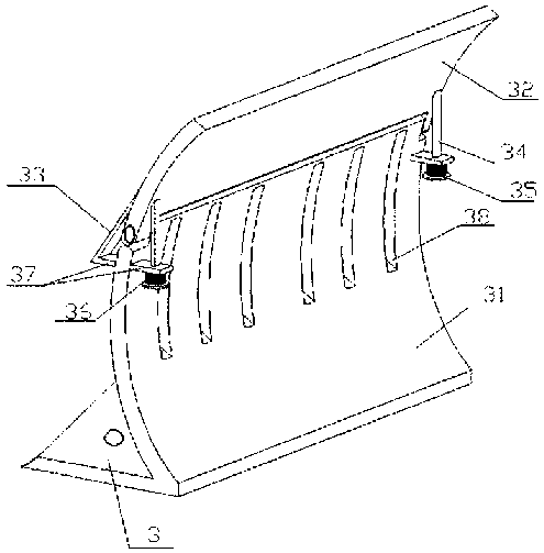
[0022] The lifting plate is arc-shaped, including a movable plate 32 and a fixed plate 31 connected to the inner wall of the drum. The bottom of the fixed plate 31 is connected with the inner wall of the drum 1 by solid welding, and the top is extended along the same curvature at the midpoint of its length. There are lugs, the bottom of the movable plate 32 is provided...


PUM


Abstract

The invention relates to a dryer material lifting mechanism. Aiming at the design of a material lifting plate in the prior art, the structure and the position distribution are improved; based on no influence on the material lifting operation, lifted material blocks are effectively prevented from falling and rupturing; and meanwhile, the drying efficiency is improved.

Description

technical field [0001] The invention relates to the technical field of drying equipment, in particular to a drying machine lifting mechanism. Background technique [0002] At present, the main part of the dryer used in the field of material drying production is an inclined rotating drum. Gears are installed on the rotating drum to drive the rotating drum to rotate. Sealing devices are installed at both ends of the rotating drum to prevent dust from leaking out. It is equipped with a feeding device and a discharge device at the lower end. At the same time, in order to accelerate the material to be evenly distributed on the drum section of the dryer and to make good contact with the drying medium, a lifting plate is installed in the drum of the dryer, which can improve the drying quality and the efficiency of the dryer. However, the above structure is prone to the following problems in the actual use process: when the moisture content of the material is too high, it is not ea...

Claims


Application Information

Patent Timeline
Patent Type & Authority Applications(China)
IPC IPC(8): F26B25/04
CPCF26B25/04
Inventor 李晓李瑞江孟华张竹青
Owner 李晓
Why Eureka
Try Eureka