Display system with optical lens and display screen and image display method thereof

An optical lens and image display technology, applied in the field of image processing, can solve the problems of image blur or ghosting, visual effect distortion of head-mounted display, etc., and achieve good visual effect.

Active Publication Date: 2014-09-03
GOERTEK OPTICAL TECH CO LTD
View PDF4 Cites 11 Cited by
  • Summary
  • Abstract
  • Description
  • Claims
  • Application Information

AI Technical Summary

Problems solved by technology

[0005] The present invention provides an image display method with an optical lens and a display screen in order to solve the problems of distortion of the visual effect of the existing head-mounted display and image blurring or ghosting, which can overcome the above-mentioned problems

Method used


Image

  • Display system with optical lens and display screen and image display method thereof
  • Display system with optical lens and display screen and image display method thereof
  • Display system with optical lens and display screen and image display method thereof

Examples


Embodiment 1

[0053] Embodiment 1, this embodiment provides an image display method with an optical lens and a display screen, see Figure 7 and Figure 8 , 9 shown, including the following steps:

[0054] S1. Virtually reverse the optical lens according to the optical parameters of the optical lens to obtain a virtual reverse lens, the object image of the reverse lens and the object image of the optical lens are reversed;

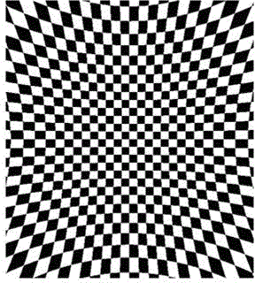
[0055] S2. According to the optical parameters of the inversion lens, respectively calculate the distortion coefficients of the RGB three color components after passing through the inversion lens, which are a1, a2, and a3;

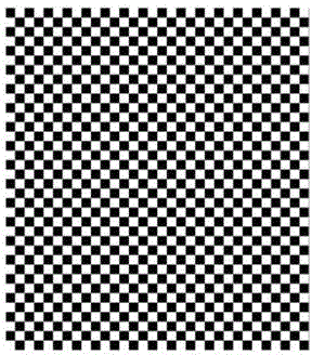
[0056] S3. Enlarge each pixel of a pre-display image by a1, a2, and a3 times, respectively, to obtain the RGB three color components after the distortion of each pixel, and form a compensated image;

[0057] S4. After the compensated image is output to the display screen for display, it passes through the optical lens and is displayed as a normal...

Embodiment 2

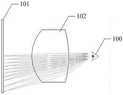
[0087] Embodiment 2, based on an image display method with an optical lens and a display screen in Embodiment 1, this embodiment provides a display system for an image display method, such as Figure 8 and 9 As shown, it includes an optical lens 102, a display screen 101 arranged in front of the optical lens 102, and an image adjustment module 103 connected to the display screen 101, and the image adjustment module 103 includes:

[0088] A virtual inversion lens unit, configured to virtually invert the optical lens according to the optical parameters of the optical lens to obtain a virtual inversion lens, the object image of the inversion lens is the same as the object image of the optical lens reversed;

[0089] A distortion coefficient calculation unit, which is used to calculate the distortion coefficients of the RGB three color components after passing through the inversion lens according to the optical parameters of the inversion lens, which are a1, a2, and a3;

[0090]...


PUM


Abstract

The invention discloses a display system with an optical lens and display screen and an image display method of the display system. The image display method comprises the following steps that first, the optical lens is reversed in a virtual mode according to the optical parameters of the optical lens to obtain a virtual reversed lens, the objective image of the reversed lens is reversed to the objective image of the optical lens; second, the distortion coefficients of the three color components of RGB are calculated according to the optical parameters of the reverted lens after the color components pass through the reverted lens, and serve as a1, a2 and a3 respectively; third, pixel points of a predictive display image are amplified a1 times, a2 times and a3 times respectively, so that the three RGB color components of each pixel point is obtained to form a compensatory image after the pixel point is distorted, and a compensatory image is formed; fourth, after the compensatory image is output to the display screen and displayed, the compensatory image is displayed as a normal image through the optical lens. According to the display system with the optical lens and the display screen and the image display method of the display system, the problem that blur or ghosting or distortion of an image may happen is solved, and an algorithm can be carried out fast and conveniently.

Description

technical field [0001] The invention belongs to the technical field of image processing, and in particular relates to a display system with an optical lens and a display screen and an image display method thereof. Background technique [0002] As an emerging technology in recent years, head-mounted display (HMD) is a kind of enlarged image on the ultra-micro display screen, which projects the image on the user's retina, and then presents a large-screen image in the eyes of the viewer. Head-mounted displays are currently widely used in many aspects such as industry, military affairs, literature and art, and entertainment. [0003] FIG. 1 is a schematic diagram of the optical path of the current head-mounted display, as shown in FIG. 1 , wherein the human eye 100 can watch the image formed on the straight flat-panel display 101 through the eyepiece 102. Due to the refraction of the light through the eyepiece 102, certain distortion will be generated, such as figure 2 , ima...

Claims


Application Information

Patent Timeline
Patent Type & Authority Applications(China)
IPC IPC(8): G02B27/01
Inventor 赵博刚王晨阳杨春周宏伟
Owner GOERTEK OPTICAL TECH CO LTD
Why Eureka
Try Eureka