A reactive compensation cabinet and a control method for reactive compensation units of the reactive compensation cabinet

A compensation unit and control method technology, applied in reactive power compensation, reactive power adjustment/elimination/compensation, etc., can solve communication conflicts, reactive power compensation cabinet loses comprehensive measurement and control functions, etc., to achieve reactive power compensation Effect

Active Publication Date: 2014-09-03
SHANGHAI WITELEC
View PDF4 Cites 5 Cited by
  • Summary
  • Abstract
  • Description
  • Claims
  • Application Information

AI Technical Summary

Problems solved by technology

[0005] The technical problem to be solved by the present invention is to overcome the fact that multiple reactive power compensation units sharing one main control unit in the prior art will cause the reactive power compensation cabinet to lose the comprehensive measurement and control function when the main control unit quits operation for some reason and if The use of multi-host communication will cause communication conflicts, and a control method for a reactive power compensation cabinet and its reactive power compensation unit is provided that does not need to configure a separate main control unit and has the function of only one host running at a time.

Method used


Image

  • A reactive compensation cabinet and a control method for reactive compensation units of the reactive compensation cabinet
  • A reactive compensation cabinet and a control method for reactive compensation units of the reactive compensation cabinet

Examples


Embodiment Construction

[0033] The present invention is further illustrated below by means of examples, but the present invention is not limited to the scope of the examples.

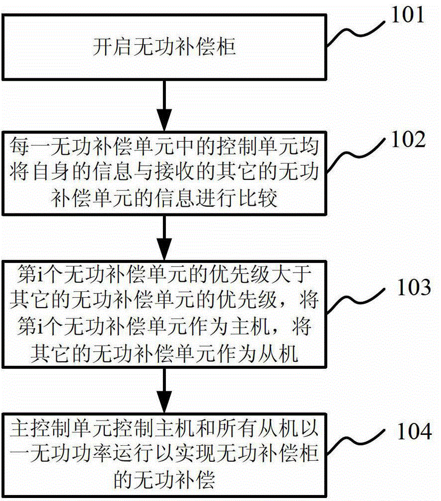
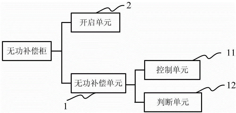
[0034] like figure 1 As shown, the present invention provides a control method of a reactive power compensation unit in a reactive power compensation cabinet, the reactive power compensation cabinet includes N reactive power compensation units, each reactive power compensation unit includes a control unit, and each control unit Both are used to control the operation of the reactive power compensation unit where it is located, assuming 1≤i≤N, the control method includes:

[0035] Step 101, open the reactive power compensation cabinet;

[0036] Step 102, each reactive power compensation unit exchanges information with other (N-1) reactive power compensation units, and the control unit in each reactive power compensation unit communicates its own information with the received other (N-1) reactive power compensation units -1) Co...


PUM


Abstract

The invention provides a reactive compensation cabinet and a control method for reactive compensation units of the reactive compensation cabinet. The control method comprises the following steps: starting the reactive compensation cabinet; each reactive compensation unit being in information interaction with other reactive compensation units, and a control unit of each reactive compensation unit comparing information of itself with the received information of the other reactive compensation units; judging the priority of each reactive compensation unit based on the information; if the priority of the ith reactive compensation unit is larger than the priority of the other reactive compensation units, taking the ith reactive compensation unit as a master machine and the control unit of the ith reactive compensation unit as a master control unit, and taking the other reactive compensation units as slave machines and the control units of the other reactive compensation units as slave control units; and the master control unit controlling the master machine and all the slave machines to be in reactive power operation so as to realize reactive compensation of the reactive compensation cabinet. The master control unit does not need to be configured separately, and only one master machine runs every moment; and the reactive compensation of the reactive compensation cabinet is realized.

Description

technical field [0001] The invention relates to a reactive power compensation cabinet provided with a plurality of reactive power compensation units, in particular to a control method of the reactive power compensation units in the reactive power compensation cabinet and the reactive power compensation cabinet. Background technique [0002] There are generally multiple reactive power compensation units installed in the reactive power compensation cabinet used in the power system. According to the actual needs of the site, the above multiple reactive power compensation units should be comprehensively measured and controlled, and the input or withdrawal of certain components should be realized according to the site needs. The operation of one or more reactive power compensation units to achieve the expected purpose of reactive power compensation, so that the power system can achieve the goal of economical and safe operation. Therefore, the above-mentioned multiple reactive pow...

Claims


Application Information

Patent Timeline
Patent Type & Authority Applications(China)
IPC IPC(8): H02J3/18
CPCY02E40/30
Inventor 郑雷
Owner SHANGHAI WITELEC
Why Eureka
Try Eureka