
Mounting tool for valve bearings in various sizes

An installation tool, multi-dimensional technology, applied in the oil field

Inactive Publication Date: 2014-09-10
CHENGDU DAMO PETROLEUM MACHINERY GRP
View PDF6 Cites 3 Cited by
  • Summary
  • Abstract
  • Description
  • Claims
  • Application Information

AI Technical Summary

Problems solved by technology

[0003]The present invention overcomes the deficiencies of the prior art and provides a multi-size valve bearing installation tool, which solves the problem that previous tools cannot be used for different types of valve bearing installation , resulting in inconvenience of installation and increased cost

Method used


Image

  • Mounting tool for valve bearings in various sizes
  • Mounting tool for valve bearings in various sizes

Examples


Embodiment 1

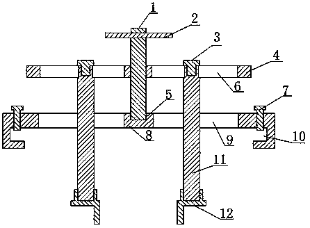
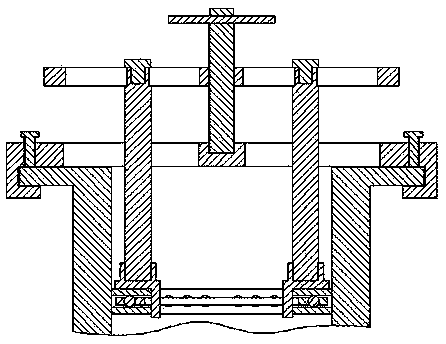
[0021] Such as figure 1 , figure 2 Installation tools for valve bearings of multiple sizes shown, including:

[0022] The horizontal positioning plate 8 is provided with a positioning groove 5 in the middle of the horizontal positioning plate 8, and the horizontal positioning plate 8 is located at both ends of the positioning groove 5 and is equidistantly provided with a limiting groove 9;

[0023] The linkage plate 4 is provided with a threaded through hole in the middle of the linkage plate 4, and movable grooves 6 are symmetrically arranged on both sides of the linkage plate 4 with the central axis of the threaded through hole as the center;

[0024] The lower end of the screw 1 is positioned in the positioning groove 5 after the screw 1 cooperates with the threaded through hole of the linkage plate 4;

[0025] Vertical straight rod 11, vertical straight rod 11 equidistantly arranged on both sides of screw rod 1, and the upper end of described vertical straight rod 11 p...

Embodiment 2

[0031] This embodiment adds the following structure on the basis of Embodiment 1: both ends of the horizontal positioning plate 8 are bent to form a bayonet 10 , and the horizontal positioning plate 8 is provided with a locking nut 7 corresponding to the bayonet 10 .

[0032] In this embodiment, in order to facilitate the fixing of the horizontal positioning plate 8, reduce the difficulty of tool fixing, and avoid the trouble of installing the fixing device, both ends of the horizontal positioning plate 8 are bent to form a bayonet 10, and the bayonet 10 is clamped on the upper end of the valve. The horizontal positioning plate 8 can be firmly fixed on the flange plate and locked by the lock nut, which is convenient for bearing installation.

Embodiment 3

[0034] In this embodiment, the following structure is optimized on the basis of embodiment 1 or embodiment 2, specifically: the lower end of the positioning block 12 has an L-shaped structure, and the upper end of the positioning block 12 is screwed to the lower end of the vertical rod 11 .

[0035] In this embodiment, the lower end of the positioning block 12 has an L-shaped structure, and the gaps of the L-shaped structures of the two positioning blocks 12 are arranged in reverse. When positioning, one side of the L-shaped structure of the bearing is located at the upper end of the bearing, and the other side is located at the inner circumference of the bearing. Clamp and position the bearing to keep it horizontal, and the bearing can be pressed tightly, so that the fixing and positioning effects are good.


PUM


Abstract

The invention discloses a mounting tool for valve bearings in various sizes. The mounting tool comprises a horizontal positioning plate, a linkage plate, a screw, vertical straight bars and positioning blocks, wherein a positioning groove is formed in the horizontal positioning plate; limiting grooves are equidistantly formed in the horizontal positioning plate in positions at two ends of the positioning groove; a threaded through hole is formed in the middle of the linkage plate; moving grooves are formed in two sides of the linkage plate and are centrosymmetric about the central axis of the threaded through hole; the screw is matched with the threaded through hole of the linkage plate and penetrates through the linkage plate to be positioned in the positioning groove; the vertical straight bars are equidistantly arranged on two sides of the screw; the upper ends of the vertical straight bards are fixed in the moving grooves through fastening screws after the vertical straight bars penetrate through the limiting grooves; the positioning blocks are movably connected with the lower ends of the vertical straight bars. The mounting tool can be used for mounting different models of valve bearings, and reduces the inconvenience of tool changing and the cost of tool manufacturing.

Description

technical field [0001] The invention relates to a petroleum valve assembly tool, which belongs to the petroleum field, and more specifically relates to a multi-size valve bearing installation tool. Background technique [0002] Some petroleum valves need to fill thrust ball bearings inside the valve seat before installing the valve stem to reduce the movement friction of the valve stem. When installing the thrust ball bearing, put the seat ring of the thrust ball bearing, the steel ball cage assembly and the shaft ring into the valve stem mounting hole in sequence, and then hit the upper end of the shaft ring with a heavy object to seal the three parts. However, since the seat ring, steel ball cage assembly and shaft ring are prone to inclination when placed, the three are easily stuck in the hole when knocked, and the bearing is also easily damaged. It is necessary to adjust the seat ring, steel ball cage assembly and shaft ring every time before knocking. Not only the ins...

Claims


Application Information

Patent Timeline
Patent Type & Authority Applications(China)
IPC IPC(8): B25B27/073
CPCB25B27/062
Inventor 贺昶明
Owner CHENGDU DAMO PETROLEUM MACHINERY GRP
Learn More