Image forming device

An image and latent image carrier technology, which is applied to the electrical recording process using the charge pattern, equipment and instruments using the charge pattern electrical recording process, etc., can solve the problem of line thinning and other problems, and achieve the suppression of image density unevenness Effect

Inactive Publication Date: 2014-09-10
RICOH KK
View PDF9 Cites 2 Cited by
  • Summary
  • Abstract
  • Description
  • Claims
  • Application Information

AI Technical Summary

Problems solved by technology

In this way, when the amount of toner adhered to the line image is insufficient when the amount of developer is absorbed significantly less, the line becomes thinner.

Method used


Image

  • Image forming device
  • Image forming device
  • Image forming device

Examples


Embodiment Construction

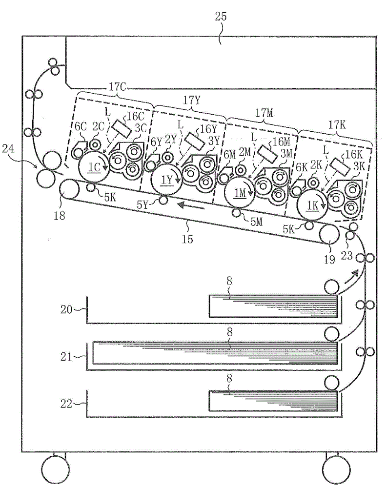
[0032] Hereinafter, an embodiment of an electrophotographic color printer (hereinafter simply referred to as a printer) will be described as an image forming apparatus to which the present invention is applied. First, the basic configuration of the printer according to the embodiment will be described. figure 1 Shown is a schematic configuration diagram of the printer according to the embodiment. This printer includes four imaging units 17K, M, Y, and C for forming toner images of K (black), M (magenta), Y (yellow), and C (cyan). In addition, it also includes a first paper feed cassette 22, a second paper feed cassette 21, a third paper feed cassette 20, a paper feed path, a registration roller pair 23, a transfer unit, a fixing device 24, and a stacking section 25 etc. In addition, the appended characters K, M, Y, and C of each code represent members for black, magenta, yellow, and cyan, respectively.

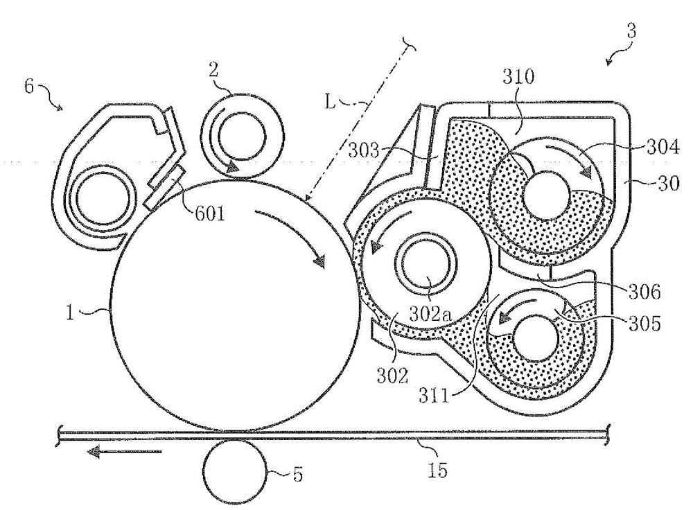
[0033] The imaging units 17K, M, Y, and C include drum-shaped photore...


PUM


Abstract

The present invention provides an image forming device which is capable of inhibiting image concentration dis-uniformity on one hand, and preventing a line dust and a line from diming on the other hand when printing images with high image area rate. The image forming device comprises a toner concentration sensor (390) for the concentration of the toner in a detection recycling agent accommodation chamber (311), and an engine control portion which adjusts a write light intensity of an electro-static latent image of a photoreceptor according to an output difference deltaVt of an output voltage of the toner concentration sensor (390) when two screw rod components (304, 305) are driven by a normal rotation speed and an output voltage of the toner concentration sensor (390) when the two screw rod components (304, 305) are driven by speed lower than the normal rotation speed.

Description

technical field [0001] The present invention relates to an image forming apparatus including a latent image carrier provided with a photoreceptor etc., a latent image writing mechanism such as a laser writing device for writing a latent image into the latent image carrier, An imaging mechanism of a developing mechanism such as a developing device that develops a latent image on a latent image carrier. Background technique [0002] Conventionally, the image forming apparatus described in Patent Document 1 is generally known as such an image forming apparatus. Figure 16 Shown is a configuration diagram of a photoreceptor 910 and a developing device 901 in the image forming apparatus described in Patent Document 1. FIG. In this figure, an electrostatic latent image is formed on the surface of a photoreceptor 910 by a known electrophotographic process, and the electrostatic latent image is developed by a developing device 901 to become a toner image. The developing device 901 ...

Claims


Application Information

Patent Timeline
IPC IPC(8): G03G15/00G03G21/12
Inventor 尾崎直幸金谷秀彰木寺亮太关口翔山田达巳
Owner RICOH KK
Why Eureka
Try Eureka