
Electrophotographic apparatus having having temperature dependent photosensitive member

a photosensitive member and electrophotography technology, applied in the field of electrophotography apparatus, can solve the problems of uneven photosensitive-member characteristics, uneven image density, and uneven image density, and achieve the effect of suppressing image density unevenness

Inactive Publication Date: 2014-09-09
CANON KK
View PDF9 Cites 0 Cited by
  • Summary
  • Abstract
  • Description
  • Claims
  • Application Information

AI Technical Summary

Benefits of technology

This approach effectively reduces image density unevenness by controlling surface temperature variations, enhancing image quality without the need for a heater, while considering environmental sustainability.

Problems solved by technology

One factor which causes the unevenness of the image density includes the unevenness (nonuniformity) of photosensitive-member characteristics such as charging characteristics and sensitivity characteristics of the electrophotographic photosensitive member.
The unevenness of the photosensitive-member characteristics originates in the unevenness (nonuniformity) of film quality and film thickness of the film which constitutes the electrophotographic photosensitive member, in many cases.
However, there is the case in which the electrophotographic apparatus having no unit for controlling the surface temperature of the electrophotographic photosensitive member, such as the heater for the electrophotographic photosensitive member, cannot sufficiently control the unevenness of the image density, and under present circumstances, the electrophotographic apparatus still has room to be improved.

Method used


Image

  • Electrophotographic apparatus having having temperature dependent photosensitive member
  • Electrophotographic apparatus having having temperature dependent photosensitive member
  • Electrophotographic apparatus having having temperature dependent photosensitive member

Examples


examples 1-1 to 1-5

[0087]The surfaces (peripheral surface) of cylindrical bodies made from aluminum with a length of 358 mm were subjected to a mirror finishing process with the use of a lathe, and a total of five cylindrical substrates with the length of 358 mm and an outer diameter of 80 mm were produced.

[0088]Subsequently, deposition films of a charge injection blocking layer, a first photoconductive layer, a second photoconductive layer, an intermediate layer and a surface layer were formed in this order on the cylindrical substrates, respectively, with the use of the apparatus for forming the deposition film as illustrated in FIG. 5, on conditions illustrated in Table 1, and thereby a total of five electrophotographic photosensitive members were manufactured. These electrophotographic photosensitive members shall be named as electrophotographic photosensitive members of Examples 1-1 to 1-5.

[0089]

TABLE 1ChargeFirstSecondinjectionphoto-photo-Inter-blockingconductiveconductivemediateSurfacelayerlaye...

examples 2-1 to 2-5

[0136]The surfaces (peripheral surface) of cylindrical bodies made from aluminum with a length of 358 mm were subjected to a mirror finishing process with the use of a lathe, and a total of five cylindrical substrates with the length of 358 mm and an outer diameter of 108 mm were produced.

[0137]Subsequently, deposition films of a charge injection blocking layer, a first photoconductive layer, a second photoconductive layer, an intermediate layer and a surface layer were formed in this order on the cylindrical substrates, respectively, with a method similar to that for Examples 1-1 to 1-5, and thereby a total of five electrophotographic photosensitive members were manufactured. These electrophotographic photosensitive members shall be named as the electrophotographic photosensitive members of Examples 2-1 to 2-5.

[0138]Subsequently, the temperature dependence (αb) of the sensitivity characteristics of each of the manufactured electrophotographic photosensitive members was measured wit...

examples 3-1 to 3-3

[0171]The surfaces (peripheral surface) of cylindrical bodies made from aluminum with a length of 358 mm were subjected to a mirror finishing process with the use of a lathe, and a total of three cylindrical substrates with the length of 358 mm and an outer diameter of 80 mm were produced.

[0172]Subsequently, deposition films of a charge injection blocking layer, a first photoconductive layer, a second photoconductive layer, an intermediate layer and a surface layer were formed in this order on the cylindrical substrates, respectively, with a method similar to that for Examples 1-1 to 1-5 except for the number of electrophotographic photosensitive members, and thereby a total of three electrophotographic photosensitive members were manufactured. These electrophotographic photosensitive members shall be named as electrophotographic photosensitive members of Examples 3-1 to 3-3.

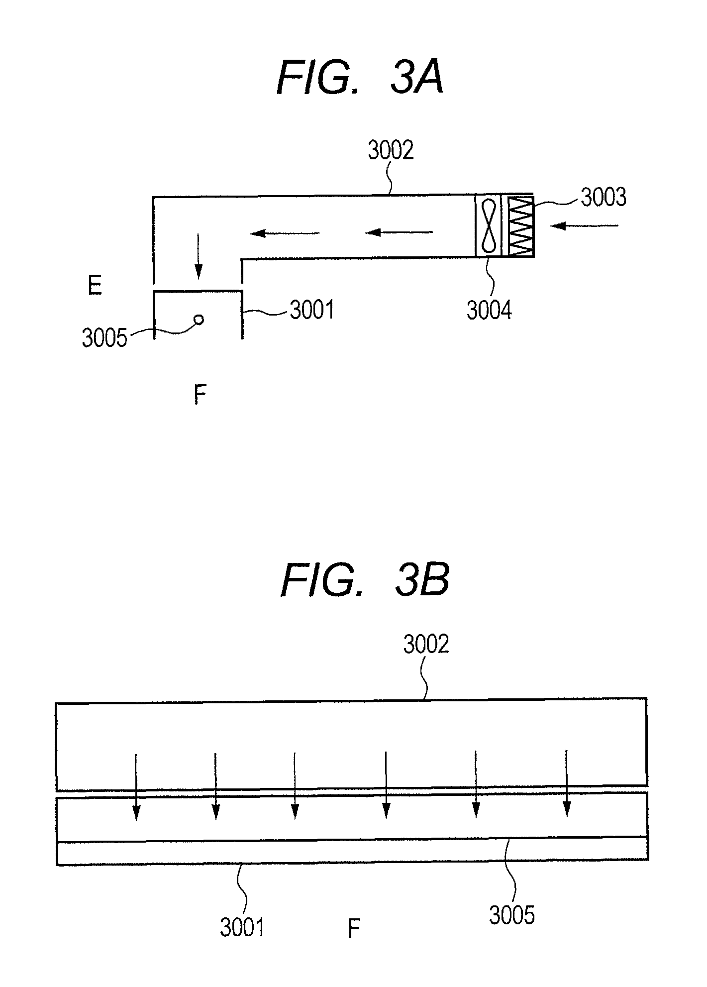
[0173]Incidentally, in the present Example, a gas pipe 8002 having gas blowing holes 8001 distributed therein...


PUM


Abstract

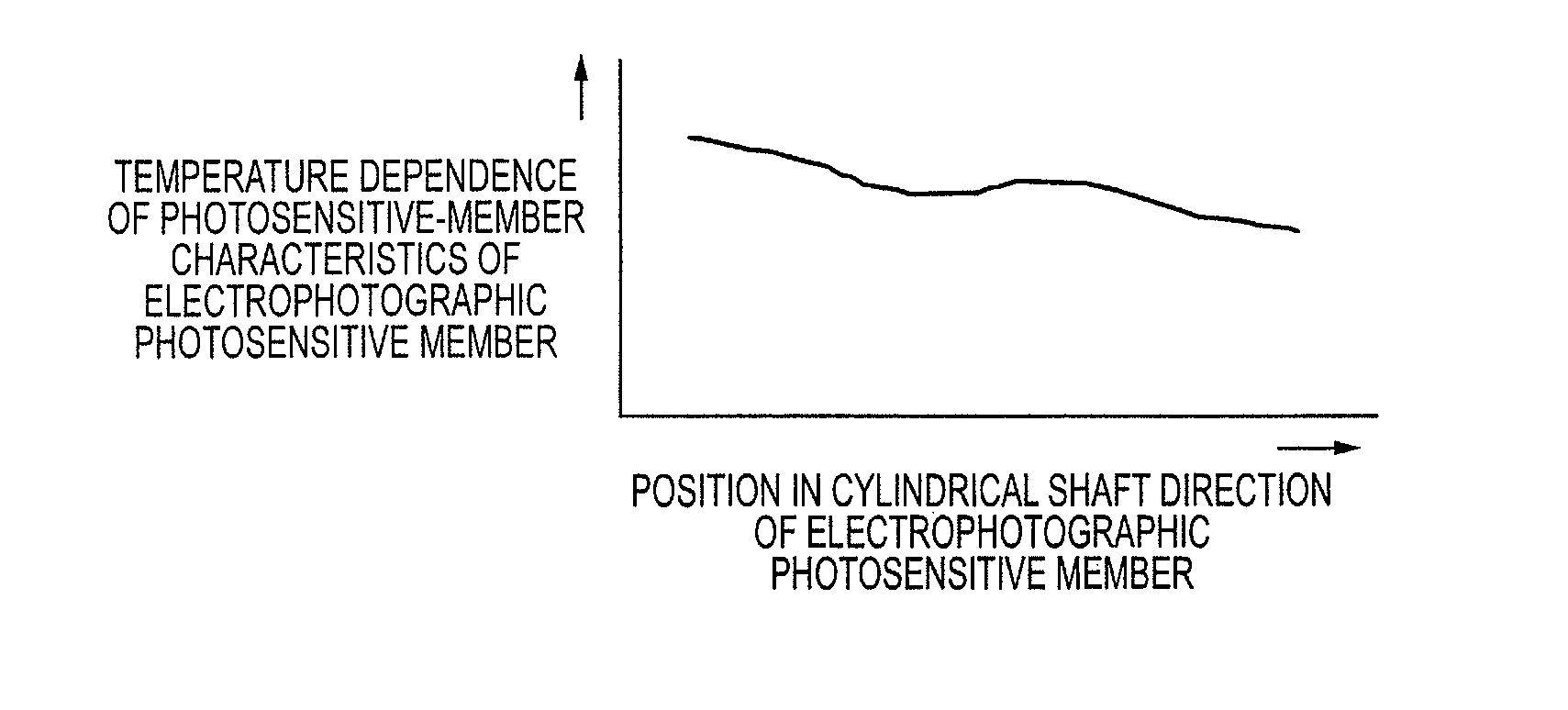
An electrophotographic apparatus does not have a unit for maintaining a uniform surface temperature of an electrophotographic photosensitive member through its surface. The electrophotographic photosensitive member has temperature dependent characteristics and is equally divided into two regions in a cylindrical shaft direction such that absolute values of the temperature dependence of the photosensitive-member characteristics in the two regions are not the same. The electrophotographic photosensitive member is arranged so that when, among the two regions, a region which has a smaller absolute value of the temperature dependence of the photosensitive-member characteristics is defined as a first region, and a region which has a larger absolute value of the temperature dependence of the photosensitive-member characteristics is defined as a second region. The change of the surface temperature of the first region becomes larger than the change of the surface temperature of the second region when an image is formed by the electrophotographic apparatus.

Description

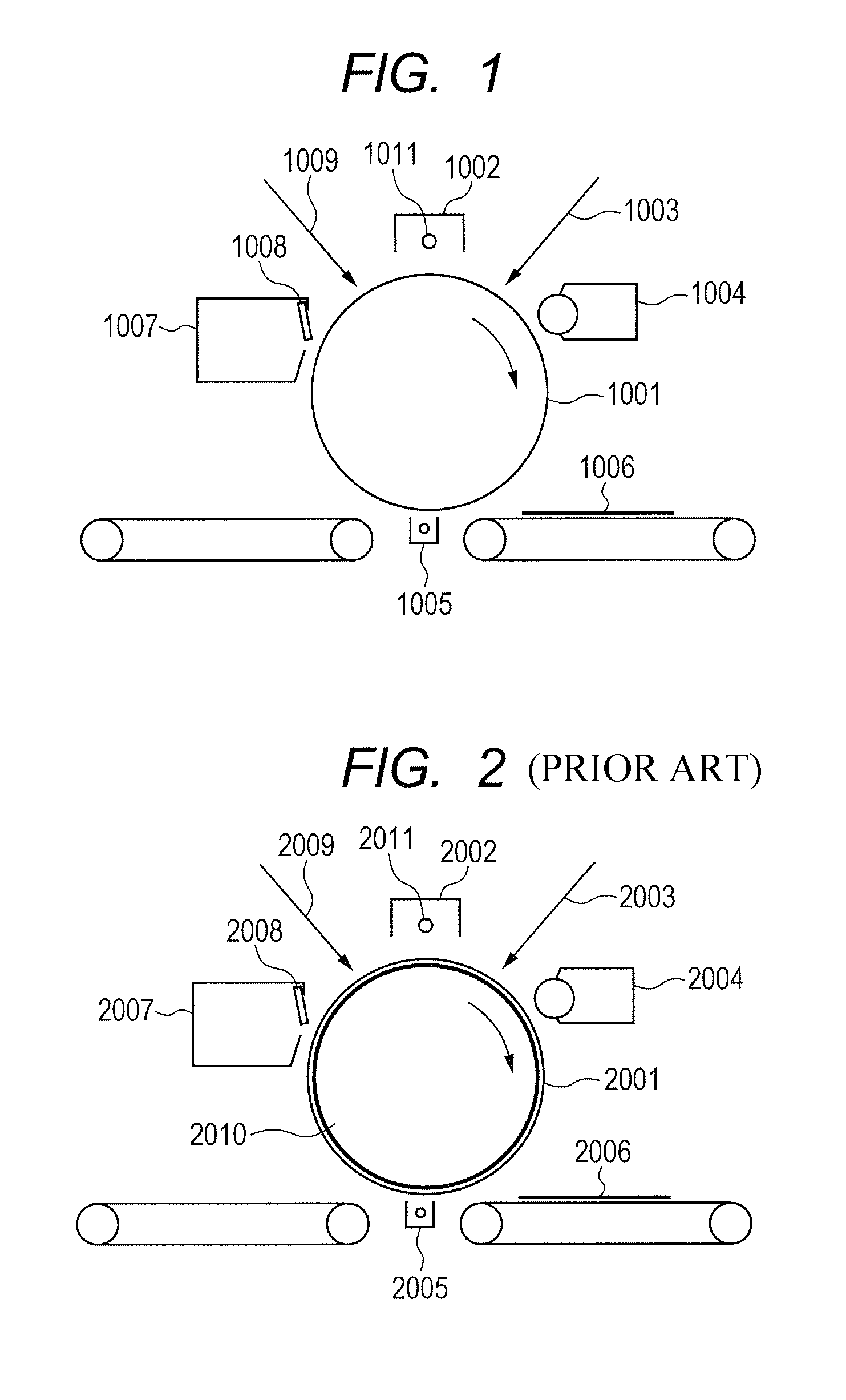
BACKGROUND OF THE INVENTION[0001]1. Field of the Invention[0002]The present invention relates to an electrophotographic apparatus.[0003]2. Description of the Related Art[0004]An electrophotographic apparatus is widely used, for instance, for a copying machine, a facsimile and a printer. In addition, as an electrophotographic photosensitive member which is used for the electrophotographic apparatus, an electrophotographic photosensitive member having a photoconductive layer (photosensitive layer) formed from amorphous silicon thereon (amorphous-silicon electrophotographic photosensitive member) is well known.[0005]FIG. 2 is a view illustrating an example of a conventional electrophotographic apparatus having a heater for an electrophotographic photosensitive member.[0006]In the electrophotographic apparatus illustrated in FIG. 2, an electrophotographic photosensitive member 2001 has a heater 2010 for an electrophotographic photosensitive member installed therein, and the heater contr...

Claims


Application Information

Patent Timeline
Patent Type & Authority Patents(United States)
IPC IPC(8): G03G15/00G03G21/20
CPCG03G15/75G03G15/0258
Inventor TAZAWA, DAISUKEOZAWA, TOMOHITOUENO, TAKANORI
Owner CANON KK
Learn More