
Developing device and image forming apparatus

a development device and image forming technology, applied in the direction of electrographic process apparatus, instruments, optics, etc., can solve the problems of uneven image density in the image formed, inability of the image forming apparatus to produce high-quality images, and inability of the developer in a compressed state to be frictionally charged to a sufficient degree, etc., to achieve the effect of suppressing image density unevenness

Active Publication Date: 2014-09-09
SHARP KK
View PDF14 Cites 0 Cited by
  • Summary
  • Abstract
  • Description
  • Claims
  • Application Information

AI Technical Summary

Benefits of technology

The solution ensures sufficient charging of developers, prevents image density unevenness, and facilitates the rapid and efficient mixing of new toner with existing developers, resulting in high-quality images with consistent density.

Problems solved by technology

However, the negative aspect of the developer conveying section is that the developer is compressed when sandwiched between the spiral blade and the side surface of the fin, and the developer in a compressed state cannot be frictionally charged to a sufficient degree.
If such an insufficiently charged developer is used, the image forming apparatus will fail to produce high-quality images.
As a result, it is difficult for the new toner to diffuse in the axial direction of the rotation shaft member, and unevenness occurs in the concentration of the toner inside the developer tank, which causes image density unevenness in the image formed using the developing device.

Method used


Image

  • Developing device and image forming apparatus
  • Developing device and image forming apparatus
  • Developing device and image forming apparatus

Examples


Embodiment Construction

[0056]Now referring to the drawings, preferred embodiments are described below.

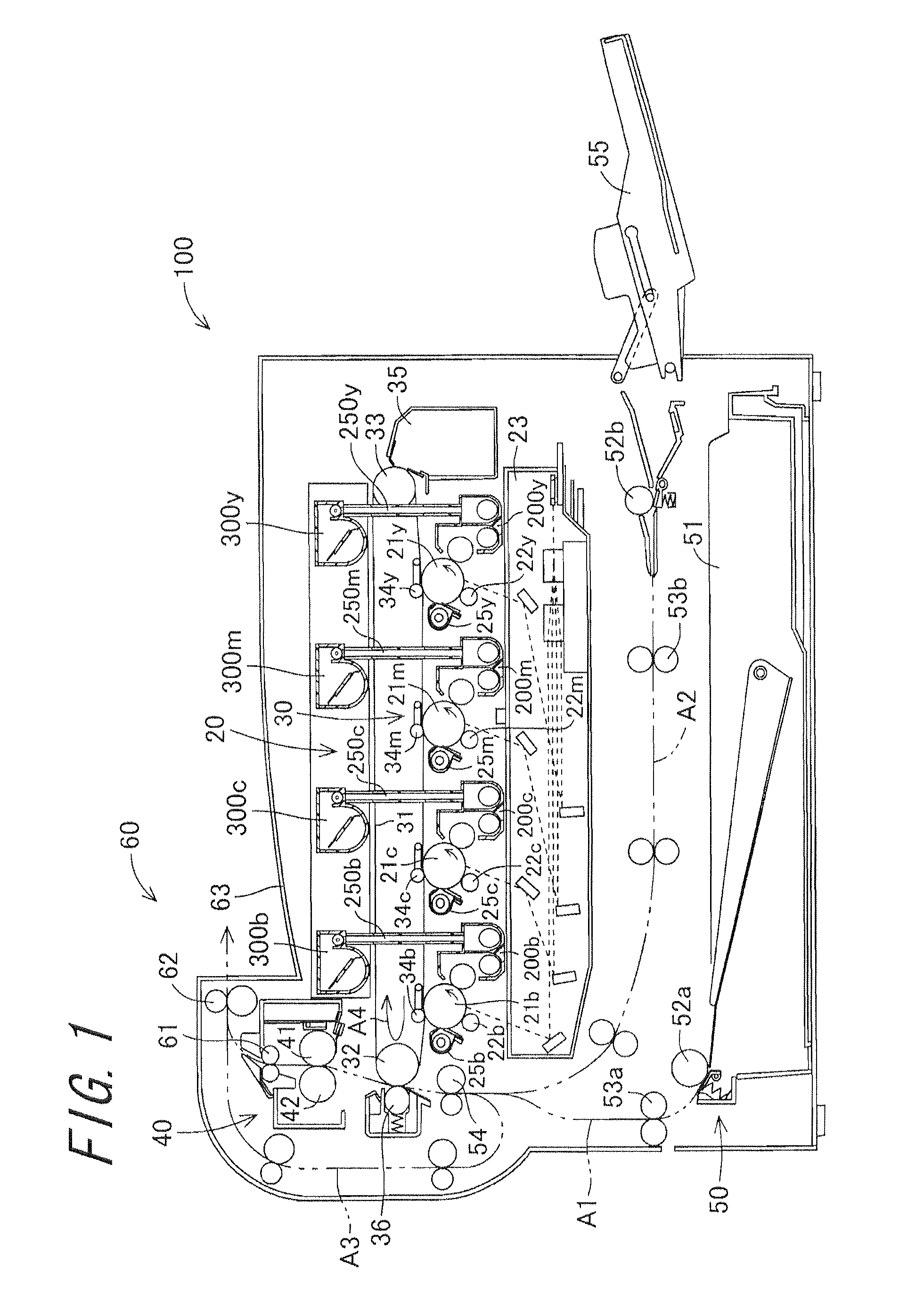
[0057]First, an image forming apparatus 100 including a developing device 200 according to an embodiment will be described. FIG. 1 is a schematic view illustrating a configuration of the image forming apparatus 100. The image forming apparatus 100 is a multi-functional peripheral having a copying function, a printing function, and a facsimile function, and forms a full color image or a monochrome image on a recording medium according to transferred image information.

[0058]The image forming apparatus 100 includes a toner image forming section 20, a transfer section 30, a fixing section 40, a recording medium feeding section 50, a discharging section 60, and a control unit section (not shown). The toner image forming section 20 includes photoreceptor drums 21b, 21c, 21m, and 21y, charging sections 22b, 22c, 22m, and 22y, an exposure unit 23, developing devices 200b, 200c, 200m, and 200y, cleaning units 25b,...


PUM


Abstract

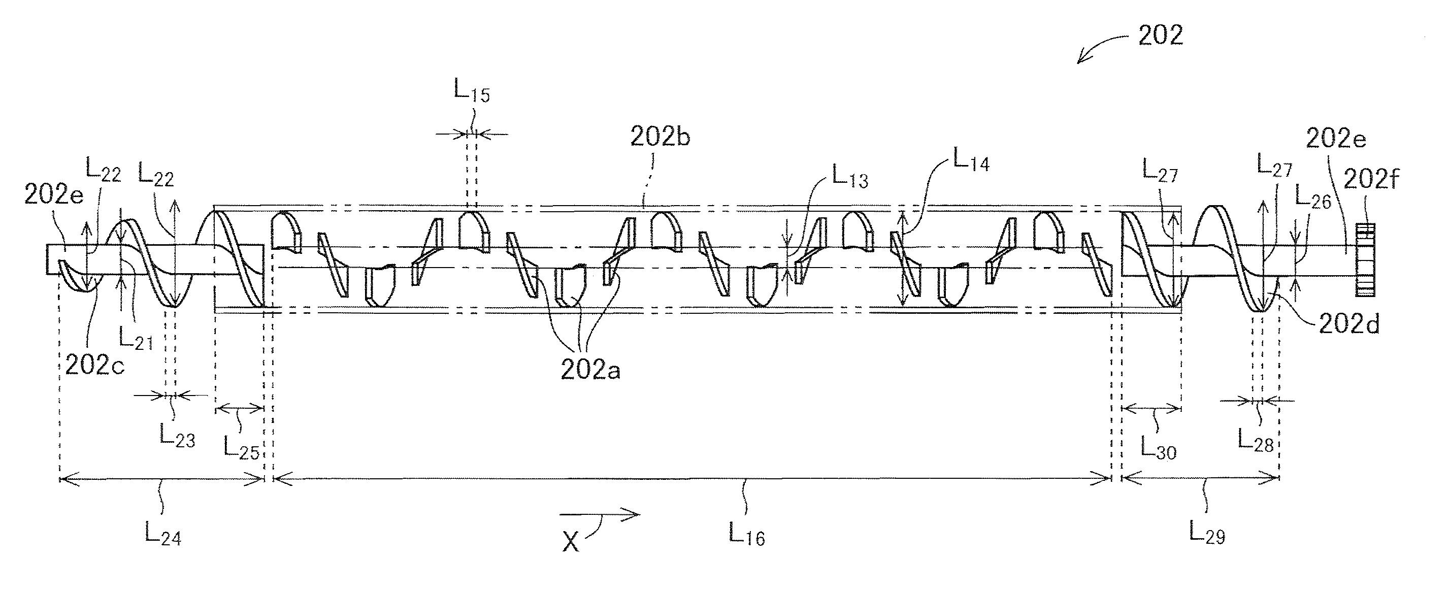
In a developing device including a developer tank and a developing roller, an internal space of the developer tank is divided into a first conveying path, a second conveying path, a first communication path and a second communication path, by a partition wall. A first developer conveying section which conveys a developer in the developer tank in a conveying direction X is disposed in the first conveying path. A second developer conveying section which conveys the developer in the developer tank in a conveying direction Y is disposed in the second conveying path. The first developer conveying section includes a plurality of inner spiral blade pieces, a rotation tube, an upstream spiral blade, a downstream spiral blade, support members, and a first gear.

Description

CROSS-REFERENCE TO RELATED APPLICATION[0001]This application claims priority to Japanese Patent Application No. 2011-40970, which was filed on Feb. 25, 2011, the contents of which are incorporated herein by reference in its entirety.BACKGROUND OF THE TECHNOLOGY[0002]1. Field of the Technology[0003]The present technology relates to a developing device and an image forming apparatus.[0004]2. Description or the Related Art[0005]Copiers, printers, facsimiles, or the like include an image forming apparatus that forms an image by electrophotography. The electrophotographic image forming apparatus forms an electrostatic latent image on a surface of an image bearing member (photoreceptor) using a charging device and an exposure device, develops the electrostatic latent image by supplying developer using a developing device, transfers the developer image on the photoreceptor to a recording medium such as recording paper using a transfer section, and fixes the developer image onto the recordi...

Claims


Application Information

Patent Timeline
Patent Type & Authority Patents(United States)
IPC IPC(8): G03G15/06G03G15/08
CPCG03G15/0893G03G2215/0822G03G2215/0132G03G2215/0838
Inventor MIHARA, KOICHINAGAI, TAKAFUMI
Owner SHARP KK
Learn More