Supercharge Your Innovation With Domain-Expert AI Agents!

Fuse wire adjusting circuit

A technology for regulating circuits and fuses, applied in logic circuits, electrical components, pulse technology, etc., can solve problems such as unstable working conditions of fuse regulating circuits, and achieve reliable control effects

Inactive Publication Date: 2014-09-10
SHAANXI EYOUNG TECH
View PDF0 Cites 4 Cited by
  • Summary
  • Abstract
  • Description
  • Claims
  • Application Information

AI Technical Summary

Problems solved by technology

[0006] In order to solve the problem of unstable working state of the traditional fuse adjustment circuit, the present invention provides a new fuse adjustment circuit with strong anti-interference ability and simple implementation

Method used


Image

  • Fuse wire adjusting circuit
  • Fuse wire adjusting circuit

Examples


Embodiment Construction

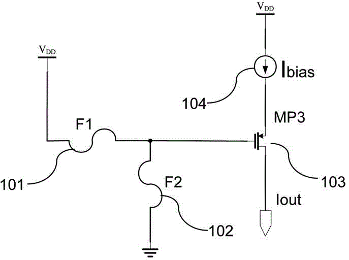
[0014] Traditional fuse adjustment circuits such as figure 1 As shown, the gate of the power MOS transistor MP3 is respectively connected to the power supply and the ground through the fuses F1 and F2. The source of the power MOS transistor MP3 is connected to the current bias Ibias, and the drain is output. Usually, because the MOS tube to be adjusted is a power MOS tube. Usually the size of the power MOS tube is very large, so its parasitic capacitance resistance is particularly large, and the source and drain current is very large. If its gate is directly connected to the power supply or ground through the fuse, the working state of the power MOS tube may be unstable, and unnecessary noise will be introduced to the entire chip.

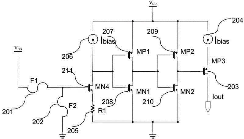
[0015] The fuse adjustment circuit of the present invention is as figure 2 As shown, the source of the power MOS transistor MP3 is connected with a current bias Ibias, and the gate of the MOS transistor MP3 is connected with two stages of inver...


PUM


Abstract

The invention provides a fuse wire adjusting circuit comprising an MOS tube (203), bias current (204), a fuse wire F1 (201) and a fuse wire F2 (202). The source electrode of the MOS tube (203) is connected with bias current (204). The grid electrode of the MOS tube (203) is connected with two inverters which are respectively formed by an MOS tube MP1 (207) and an MOS tube MN1 (208), and an MOS tube MP2 (209) and an MOS tube MN2 (210). A fuse wire adjusting MOS tube (211) is connected before the inverter formed by the MOS tube MP1 (207) and the MOS tube MN1 (208). Finally the grid electrode of the fuse wire adjusting MOS tube (211) is respectively connected with a power supply and grounded via the fuse wire F1 (201) and the fuse wire F2 (202). The source electrode of the fuse wire adjusting MOS tube (211) is connected with current bias (206). The size of the fuse wire adjusting MOS tube (211) is less than that of the MOS tube (203).

Description

technical field [0001] The invention relates to the field of integrated circuits, in particular to a fuse adjustment circuit used in analog integrated circuits. Background technique [0002] In integrated circuits, in order to reduce the cost of the chip, improve the flexibility and yield of the chip. Fuses are usually set during chip design. In the test of the chip, according to the test result or the parameter requirements of the chip setting, the circuit is adjusted through the fuse, so that the result of different settings of the chip can be achieved without remanufacturing the chip. [0003] Currently, commonly used fuse setting circuits such as figure 1 As shown, the adjustment function of the circuit is realized by directly setting the fuse on the gate of the MOS transistor to be adjusted. [0004] Such a scheme mainly has the following defects: [0005] Because the MOS tube to be adjusted may be a power MOS tube. Usually the size of the power MOS tube is very la...

Claims


Application Information

Patent Timeline
Patent Type & Authority Applications(China)
IPC IPC(8): H03K19/094
Inventor 张俊
Owner SHAANXI EYOUNG TECH
Features
  • R&D
  • Intellectual Property
  • Life Sciences
  • Materials
  • Tech Scout
  • Unparalleled Data Quality
  • Higher Quality Content
  • 60% Fewer Hallucinations
Learn More