Overload protection clamp

A technology of protective clips and fixture seats, applied in the direction of clamping, manufacturing tools, supports, etc., can solve the problems of difficult control of clamping force and damage to workpieces, and achieve the effects of simple structure, reliable workpiece clamping, and easy manufacturing

Inactive Publication Date: 2014-09-17
WUHU TIANXIONG NEW MATERIAL TECH
View PDF8 Cites 8 Cited by
  • Summary
  • Abstract
  • Description
  • Claims
  • Application Information

AI Technical Summary

Problems solved by technology

[0003] Aiming at the problem that the clamping force caused by the existing clamps is difficult to control, and the workpiece is easily damaged due to excessive clamping, the present invention provides an overload protection clamp

Method used


Image

  • Overload protection clamp
  • Overload protection clamp
  • Overload protection clamp

Examples


Embodiment 1

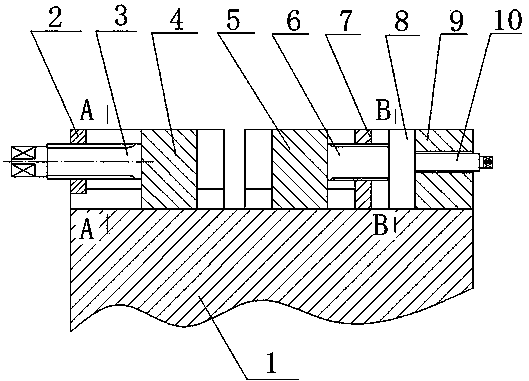
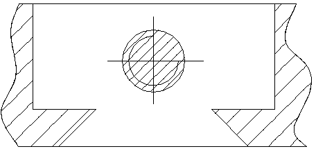
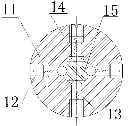
[0018] Such as figure 1 , figure 2 , image 3 As shown, the overload protection fixture includes a fixture seat 1, a left fixing block 2, a left screw rod 3, a left clamping block 4, a right clamping block 5, a right screw rod 6, and a right fixing block 7. The fixture seat 1 is provided with a dovetail groove, And the left fixed block 2 and the right fixed block 7 are arranged at both ends of the dovetail groove, and the left fixed block 2 and the right fixed block 7 are provided with threaded holes, and the left clamping block 4 and the right clamping block 5 are assembled on the fixture seat In the dovetail groove on 1, one end of the left screw rod 3 is fixedly connected with the left clamping block 4, and the other end is engaged with the thread of the left fixing block 2, and one end of the right screw rod 6 is fixedly connected with the right clamping block 5, and the other end is assembled on the right In the threaded hole of fixed block 7, safety clutch mechanism 8...


PUM


Abstract

The invention discloses an overload protection clamp and belongs to the field of clamps. The overload protection clamp comprises a clamp base, a left fixed block, a left screw rod, a left clamping block, a right clamping, a right screw rod and a right fixed block, wherein the clamp base is provided with a dovetail groove; two ends of the dovetail groove are provided with the left fixed block and the right fixed block; the overload protection clamp further comprises a safety clutch mechanism, a fixed base, a regulating rod, an outer ring, a screw, a spring, a steel ball and a square shank; the regulating rod is assembled in a threaded hole of the fixed base; the square shank is connected with the regulating rod; the screw is assembled in a threaded hole of the outer ring; the steel ball is pressed on the surface of the square shank; the spring is arranged between the screw and the steel ball. The overload protection clamp can be used for solving the problems of difficulty in clamping force control and workpiece damage caused by high excessive clamping possibility of an existing clamp, and has the advantages of simple structure, reasonable design, and easiness for manufacturing.

Description

technical field [0001] The invention belongs to the field of clamps, and more specifically relates to an overload protection clamp for preventing excessive clamping of workpieces. Background technique [0002] In the machinery manufacturing industry, machine tools are used to process various workpieces, and clamping tools are required to fix the workpieces during processing, so as to realize cutting processes such as outer circle, end face, thread and axial cutting. At present, when the existing fixture is working, in the process of frequent clamping and loosening, the tightness of the clamping of the workpiece is usually judged by hand acting on the workpiece, which consumes a lot of time, increases labor intensity, and reduces work efficiency. At the same time, because the clamping force is not easy to control, if it is too loose, the positioning effect will not be achieved, and if it is too tight, it will damage the surface of the workpiece, or even crush the workpiece. ...

Claims


Application Information

Patent Timeline
Patent Type & Authority Applications(China)
IPC IPC(8): B23Q3/00
CPCB23Q3/066
Inventor 黄雄关
Owner WUHU TIANXIONG NEW MATERIAL TECH
Why Eureka
Try Eureka