
Fixing device for manufacturing decorative plate

A technology of decorative panels and fixing devices, which is applied in the field of decoration, can solve the problems of reducing the production efficiency of decorative panels, processing deviations of decorative panels, bolt slippage and shaking, etc., to achieve the effects of avoiding deviations, preventing offsets, and improving production efficiency

Inactive Publication Date: 2021-07-20
厦门赞裁贸易有限公司
View PDF0 Cites 1 Cited by
  • Summary
  • Abstract
  • Description
  • Claims
  • Application Information

AI Technical Summary

Problems solved by technology

[0002] Decoration involves a wide range of modern life. As far as the walls of the home are concerned, most people like to use panels for decoration, and different decorative panels have different thicknesses. Decorative panels need to be processed during processing. Fixing to prevent the offset of the decorative plate. The existing fixing devices mostly use the method of manually turning the bolts to fix the decorative plate, which will lead to the phenomenon of slipping
[0003] When the existing fixing device fixes the decorative plate, it usually fixes the decorative plate by manually turning the bolts. Due to the long-term use of the fixing device and the mechanical vibration during the processing of the decorative plate, the bolts of the fixing device will be damaged. The phenomenon of slipping and sloshing leads to the offset of the decorative plate, resulting in the deviation of the processing of the decorative plate, resulting in a waste of resources. At the same time, manual screwing of the bolts is time-consuming and laborious, which reduces the production efficiency of the decorative plate processing

Method used


Image

  • Fixing device for manufacturing decorative plate
  • Fixing device for manufacturing decorative plate
  • Fixing device for manufacturing decorative plate

Examples


Embodiment Construction

[0024] The following will clearly and completely describe the technical solutions in the embodiments of the present invention with reference to the accompanying drawings in the embodiments of the present invention. Obviously, the described embodiments are only some, not all, embodiments of the present invention. Based on the embodiments of the present invention, all other embodiments obtained by persons of ordinary skill in the art without making creative efforts belong to the protection scope of the present invention.

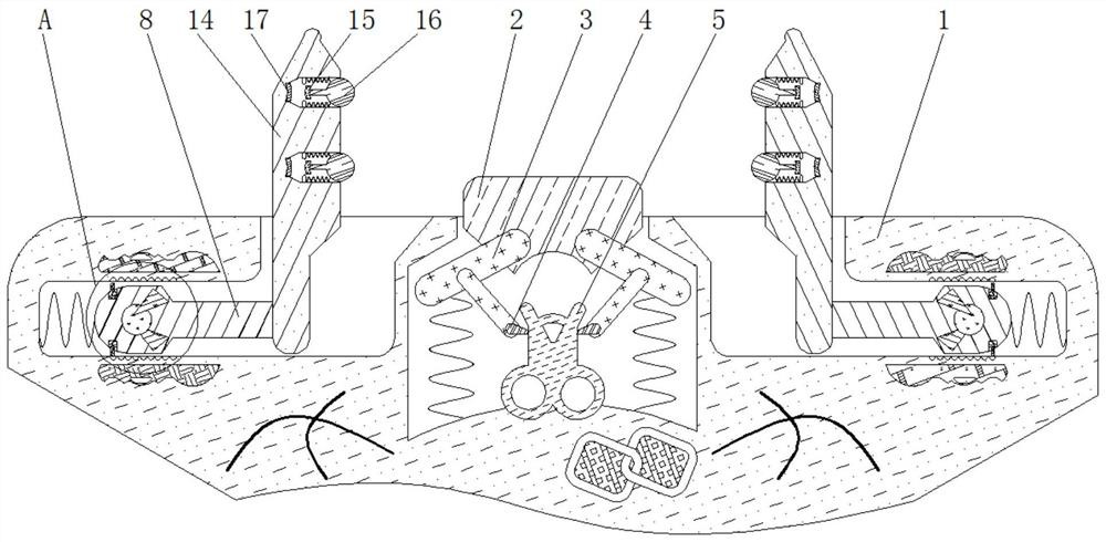
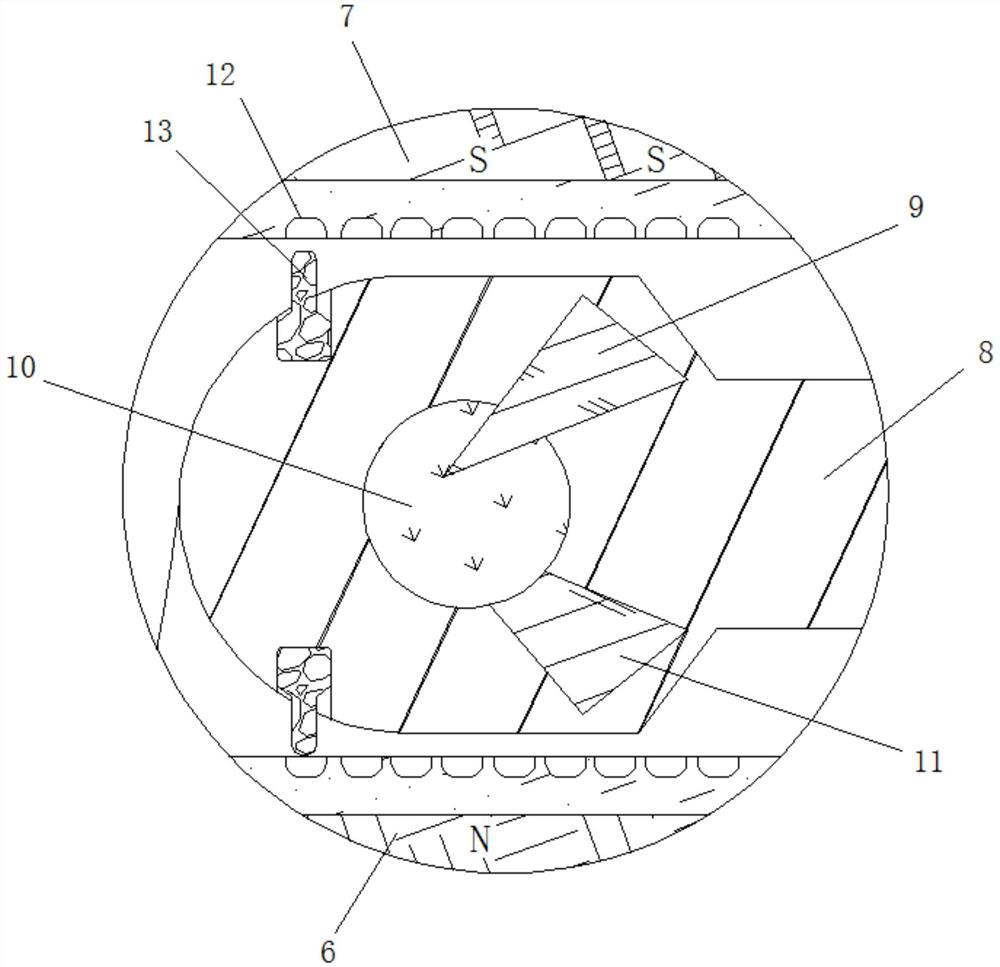
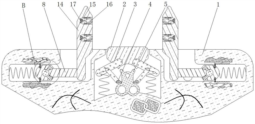
[0025] see Figure 1-4 , a fixing device for manufacturing decorative panels, comprising a housing 1, the inner wall of the housing 1 is elastically connected with a fixing frame 3, and the outer side of the fixing frame 3 is fixedly connected with a pressing block 2, the structure of the pressing block 2 is a cuboid structure, The material of the block 2 is rubber material, the pressing block 2 plays a role of extrusion, the inner side of the fixed frame 3 is...


PUM


Abstract

The invention relates to the technical field of decoration and discloses a fixing device for manufacturing a decorative plate. The fixing device comprises a shell, wherein fixed frames are elastically connected to the inner wall of the shell, a pressing block is fixedly connected to the outer sides of the fixed frames, metal sheets are fixedly connected to the inner sides of the fixed frames respectively, a slide rheostat is fixedly connected to the inner side, close to the metal sheets, of the shell, push rods are elastically connected to the inner wall of the shell, and positive electrode poles are fixedly connected to the inner walls of the push rods respectively. For the fixing device for manufacturing the decorative plate, under the action of Ampere force, when the fixing device is used for a long time and a machine vibrates in the process of processing the decorative plate, the phenomenon that a bolt of the fixing device slips and shakes is avoided, the decorative plate is prevented from deviating, and the processing deviation of the decorative plate is avoided, so that resources are saved; and manual bolt screwing is avoided, the automation degree is increased, so that the time and the labor are saved, and the production efficiency of decorative plate processing is improved.

Description

technical field [0001] The invention relates to the technical field of decoration, in particular to a fixing device for manufacturing decorative boards. Background technique [0002] Decoration involves a wide range of modern life. As far as the walls of the home are concerned, most people like to use panels for decoration, and different decorative panels have different thicknesses. Decorative panels need to be processed during processing. Fixing to prevent the offset of the decorative board. The existing fixing device mostly adopts the method of manually turning the bolt to fix the decorative board, which will lead to the phenomenon of slipping. [0003] When the existing fixing device fixes the decorative plate, it usually fixes the decorative plate by manually turning the bolts. Due to the long-term use of the fixing device and the mechanical vibration during the processing of the decorative plate, the bolts of the fixing device will be damaged. The phenomenon of slippin...

Claims


Application Information

Patent Timeline
Patent Type & Authority Applications(China)
IPC IPC(8): B25B11/00
CPCB25B11/00
Inventor 朱煜程
Owner 厦门赞裁贸易有限公司
Learn More