
Floor made from individual elements

a technology of individual elements and floor surfaces, applied in the field of floor, can solve the problems of cumbersome transportation, inability to configure level and quality floor surfaces with a high load-carrying capability, and inability to generally be used for repeated use, and achieve the effects of convenient transportation, high load-carrying capability, and easy assembly and disassembly

Inactive Publication Date: 2009-12-24
KELLNER PETER
View PDF17 Cites 27 Cited by
  • Summary
  • Abstract
  • Description
  • Claims
  • Application Information

AI Technical Summary

Benefits of technology

[0011]Due the arrangement of the peripheral grooves at the edges of the layer of light material and of connecting strips in the grooves between adjacently placed multilayer panels, the securing of the floor elements against shifting in the joint direction, as well as avoidance of offsets between adjacently laid multilayer panels, is accomplished in an easy manner. Because thin, two-dimensional sheathing of high strength and high modulus of elasticity is glued between the upper panel and the light material layer, a very high strength of the floor elements is realized, even when very thin panels and, therefore, very light floor elements are used. Such a high strength of the floor elements ensures a sufficient safety against fracture, even in the case of localized stresses which occur, for example, when shelves or cabinets, which are supported at points, are arranged. Moreover, the floor elements do not need to be laid in a bed of mortar or glued to a substrate.
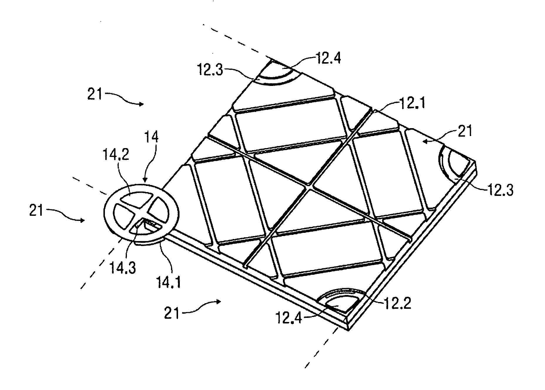
[0024]Additionally, according to a particular preferred embodiment of the invention, guide elements are disposed at the floor panel and / or at the connecting element, via which joint strips can be fixed between the floor panels. This is a simple way to fasten joint strips, which can be advantageously detached, so that joint strips can be simply assembled, disassembled and replaced.

Problems solved by technology

It was previously not possible to configure level and quality floor surfaces with a high load-carrying capability, especially when thin, and therefore light natural stone panels, are used.
When used in the usual manner for achieving the strength required, natural stone panels are relatively thick and heavy, and therefore cumbersome to transport.
For this reason, they are not generally suitable for repeated use.
Because of the danger of breakage, thin natural stone panels, which are therefore easily transported, must be glued onto a level substrate or laid in a bed of mortar, and therefore also, are also not suitable for temporary and repeated use.

Method used


Image

  • Floor made from individual elements
  • Floor made from individual elements
  • Floor made from individual elements

Examples


Embodiment Construction

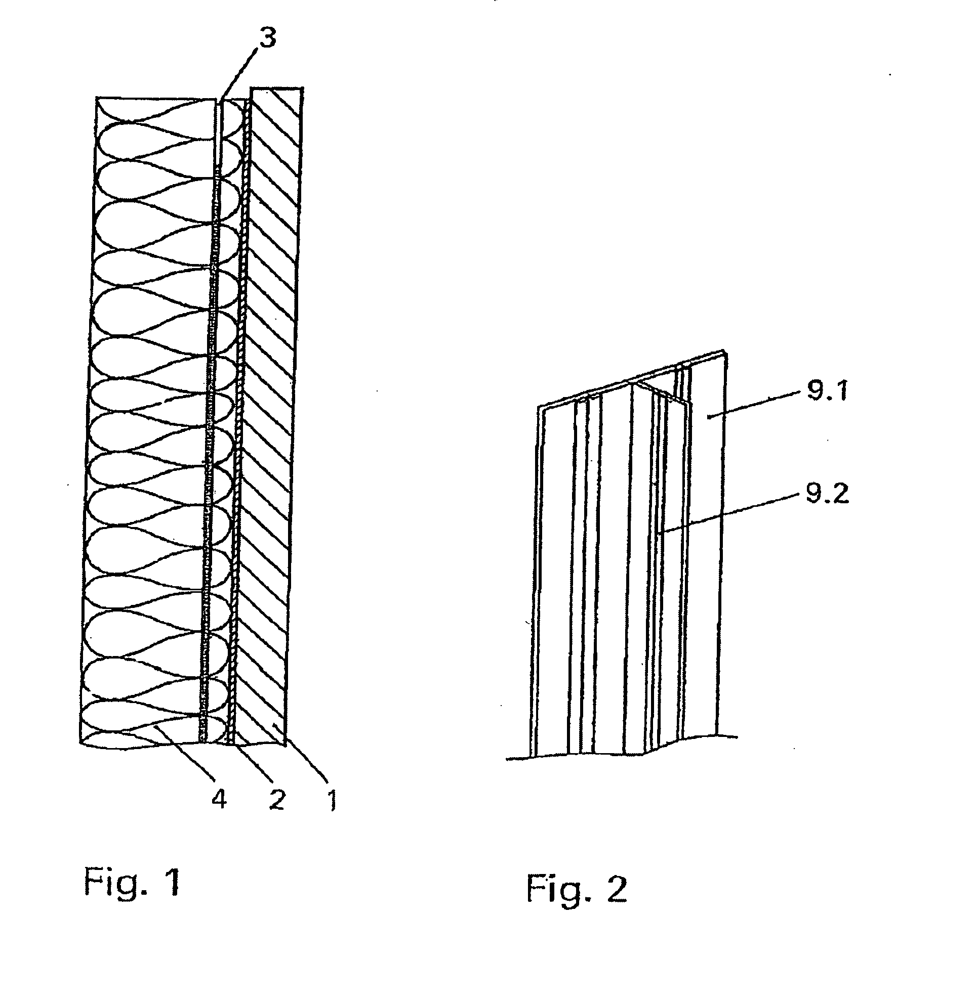
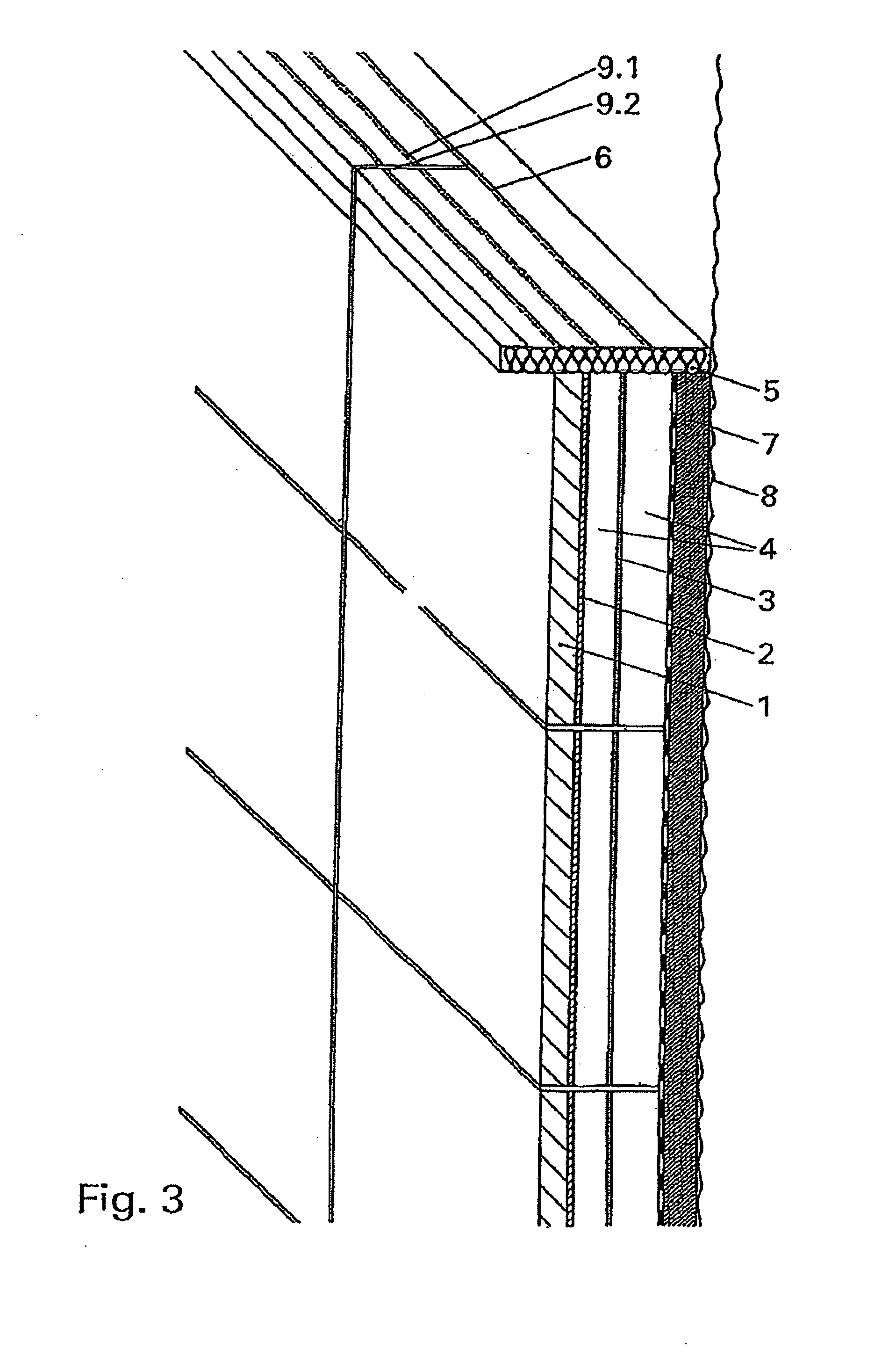
[0038]The section through an inventive, multilayer panel, is illustrated in FIG. 1, and shows a thin panel 1 of natural strength. A carbon fiber-reinforced plastic fabric of small thickness is glued two-dimensionally to an underside of the panel 1 by means of an epoxide resin, as a two dimensional sheathing 2. In addition to natural stone, the thin panel 1 may be comprised of glass, wood, or metal. In comparison with the natural stone panel, etc., the carbon fiber-reinforced plastic fabric has a relatively high modulus of elasticity. The tensile strength and the compression strength of the carbon fiber-reinforced plastic fabric are clearly greater than the compression strength of the natural stone. Beneath the carbon fiber-reinforced plastic fabric, a pressure-resistant foam layer 4, which comprises an extruded and hydrophobized Styrofoam, is glued two-dimensionally. Due to the multilayer construction shown, a multilayer panel of low weight and high bending strength is achieved. In ...


PUM

PropertyMeasurementUnit
thicknessaaaaaaaaaa
edge lengthaaaaaaaaaa
edge lengthsaaaaaaaaaa

Abstract

A multi-layer floor panel unit, which can be assembled with a plurality of similar units to form a floor which is capable of repeatedly being disassembled and reassembled at different times and / or in different locations, includes a pressure-resistant and wear-resistant upper layer; a pressure-resistant lower layer, attached to the upper layer, and having grooves at vertical edges of the lower layer; and connecting strips in the grooves, for connecting adjacent multi-layer floor panel units, the connecting strips having horizontal legs with thickened portions thereon, the thickened portions being for clamping the connecting strips in the grooves.

Description

BACKGROUND OF THE INVENTION[0001]The invention relates to a floor consisting of individual two-dimensional elements.[0002]The invention is intended, in particular, for temporarily installed floors, which can be removed following installation and use, and reused again. Such floors are required, for example, for use in exhibitions. It was previously not possible to configure level and quality floor surfaces with a high load-carrying capability, especially when thin, and therefore light natural stone panels, are used.[0003]In the state of the art, floors comprising textile coverings, which can be removed following use, are known. In this connection, the covering is removable from the floor without leaving a residue and without damaging the floor covering.[0004]According to DE 36 00 807 C2, a method is disclosed for this purpose, for which a plastic layer is disposed on both sides of a backing material, at least one side of which is glueable, impermeable to the adhesive and resistant to...

Claims


Application Information

Patent Timeline
Patent Type & Authority Applications(United States)
IPC IPC(8): E04F15/00E04C2/38E04C2/20E04B1/00E04C2/24
CPCE04B1/615E04C2/22E04C2/243E04F15/18E04F15/02E04F15/02005E04C2/384E04F2015/02116E04F15/02194E04F15/041E04F15/06E04F15/082E04F15/02016E04F15/02022
Inventor KELLNER, PETER
Owner KELLNER PETER
Learn More