Clamping device for machining farm tool parts

A clamping device and component technology, applied in workpiece clamping devices, manufacturing tools, etc., can solve the problems of unstable clamping of parts, offset or falling off, and damage of parts, so as to avoid excessive clamping and clamping. stable effect

Inactive Publication Date: 2021-03-12
刘元祥
View PDF6 Cites 1 Cited by
  • Summary
  • Abstract
  • Description
  • Claims
  • Application Information

AI Technical Summary

Problems solved by technology

At present, when processing some small parts, the workers usually hold the processing equipment and parts for processing. During the processing, the parts may shift or fall off due to the negligence of the workers, which will affect the processing effect, and the processing The equipment may cause damage to the hands holding the parts, which has certain safety hazards; when processing some large parts, clamping and fixing devices will be used. Although these devices can be clamped and fixed, they only It can clamp parts with specific shapes, so the scope of application is limited. When processing some parts with irregular shapes, stable clamping cannot be achieved, which affects work efficiency and processing effect
[0003] Aiming at the deficiencies of the prior art, the present invention provides a clamping device for processing agricultural tool parts, which has the advantages of being suitable for various shapes of parts and more convenient and stable clamping, and solves the problem of the general clamping device's application scope. Limited, the problem of not being able to stably clamp parts with irregular shapes

Method used


Image

  • Clamping device for machining farm tool parts
  • Clamping device for machining farm tool parts
  • Clamping device for machining farm tool parts

Examples


Embodiment Construction

[0022] The following will clearly and completely describe the technical solutions in the embodiments of the present invention with reference to the accompanying drawings in the embodiments of the present invention. Obviously, the described embodiments are only some, not all, embodiments of the present invention. Based on the embodiments of the present invention, all other embodiments obtained by persons of ordinary skill in the art without making creative efforts belong to the protection scope of the present invention.

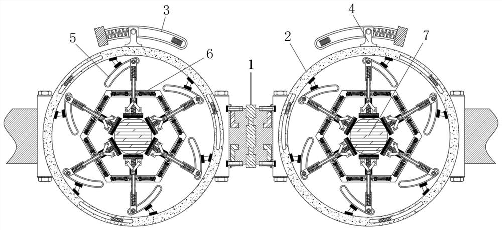
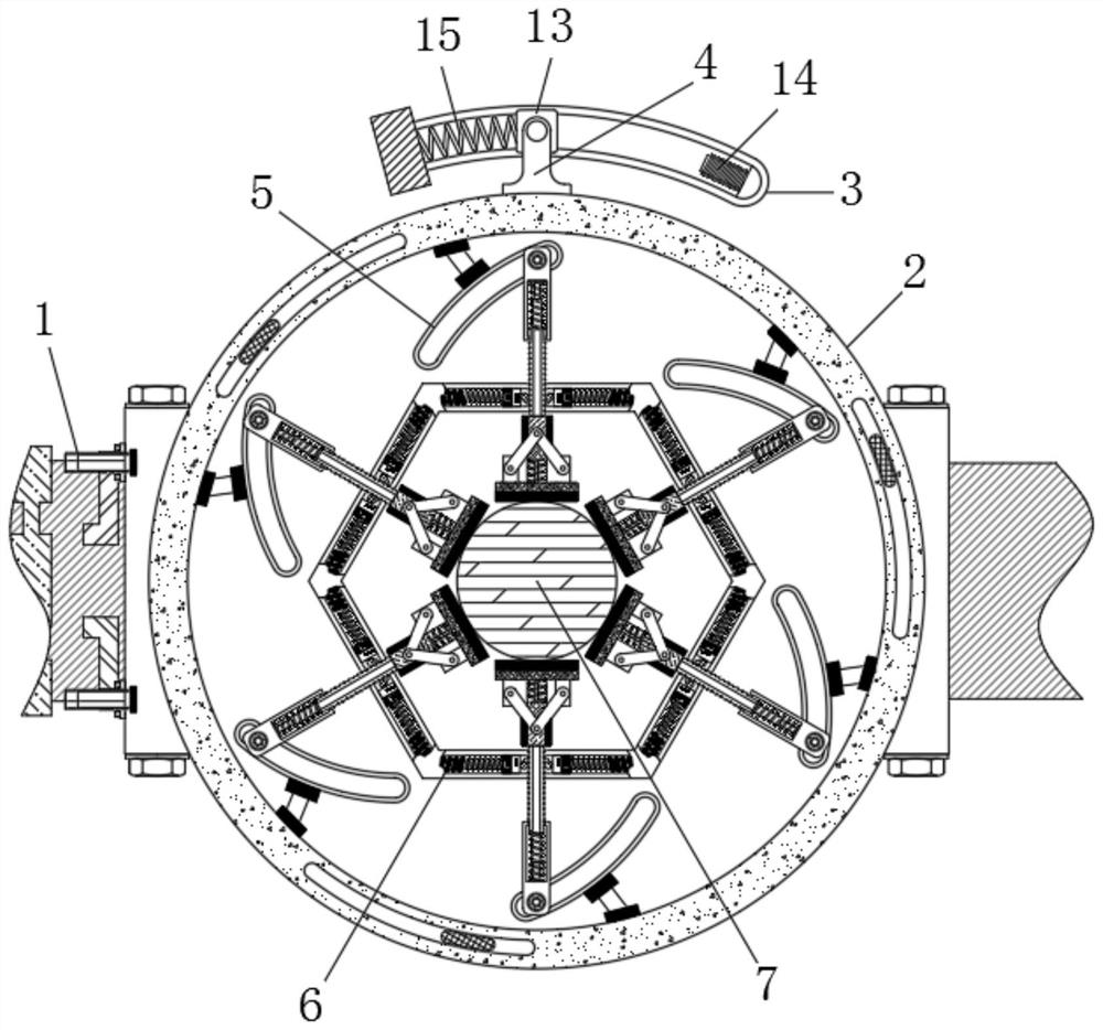
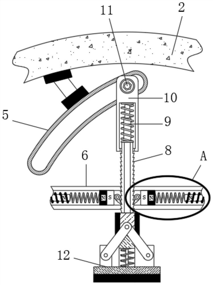
[0023] see Figure 1-4 , a clamping device for processing agricultural implement parts, comprising a mounting bracket 1, a device body 2 is rotatably connected to the body of the mounting bracket 1, and a first slide rail 3 is arranged on the outside of the device body 2, and the first slide rail A metal block 13 is slidably connected to the chute of 3, a clockwise end of the first slide rail 3 is fixedly connected with a first electromagnet 14, and the end of...


PUM


Abstract

The invention relates to the technical field of farm tool components and parts, and discloses a clamping device for machining farm tool parts. The clamping device comprises a mounting bracket, an equipment main body is rotatably connected to a frame body of the mounting bracket, a first sliding rail is arranged at the outer side of the equipment main body, and a rocking handle is fixedly connectedto the edge of the outer ring of the equipment main body; and a second sliding rail is fixedly connected to the edge of the inner ring of the equipment main body, a limiting frame is arranged at theinner side of the equipment main body, and a machining table is arranged in the center of the limiting frame. According to the clamping device for machining the farm tool parts, a second electromagnetis powered on to magnetically enhance and repel a magnet block, the magnet block is driven to slide in the direction close to a ratchet bar, a second spring is stretched, and the magnet block drivesa check pawl to gradually get close to the ratchet bar and finally abut against and be engaged with the ratchet bar; and a non-return pawl can prevent the clamping device from rebounding due to overlarge stress in the machining process, and therefore the effect of more stable clamping is achieved.

Description

technical field [0001] The invention relates to the technical field of parts and parts of agricultural implements, in particular to a clamping device for processing agricultural implement parts. Background technique [0002] Farm tools refer to the tools used in agricultural production. They are tools used by farmers to change the objects of labor in the process of agricultural production. When the parts are processed, it is necessary to fix the parts first, and then process them. At present, when processing some small parts, the workers usually hold the processing equipment and parts for processing. During the processing, the parts may shift or fall off due to the negligence of the workers, which will affect the processing effect, and the processing The equipment may cause damage to the hands holding the parts, which has certain safety hazards; when processing some large parts, clamping and fixing devices will be used. Although these devices can be clamped and fixed, they ...

Claims


Application Information

Patent Timeline
IPC IPC(8): B25B11/00
CPCB25B11/00
Inventor 刘元祥
Owner 刘元祥
Why Eureka
Try Eureka