
Conveying device

A technology of a handling device and a supply device, which is applied to tires, other household appliances, household appliances, etc., and can solve problems such as difficult transportation

Inactive Publication Date: 2014-09-24
TOYO TIRE & RUBBER CO LTD
View PDF6 Cites 3 Cited by
  • Summary
  • Abstract
  • Description
  • Claims
  • Application Information

AI Technical Summary

Problems solved by technology

However, it is quite difficult to transport the curved extruded filler strip to the molding machine while maintaining its curvature

Method used


Image

  • Conveying device
  • Conveying device
  • Conveying device

Examples


Embodiment approach

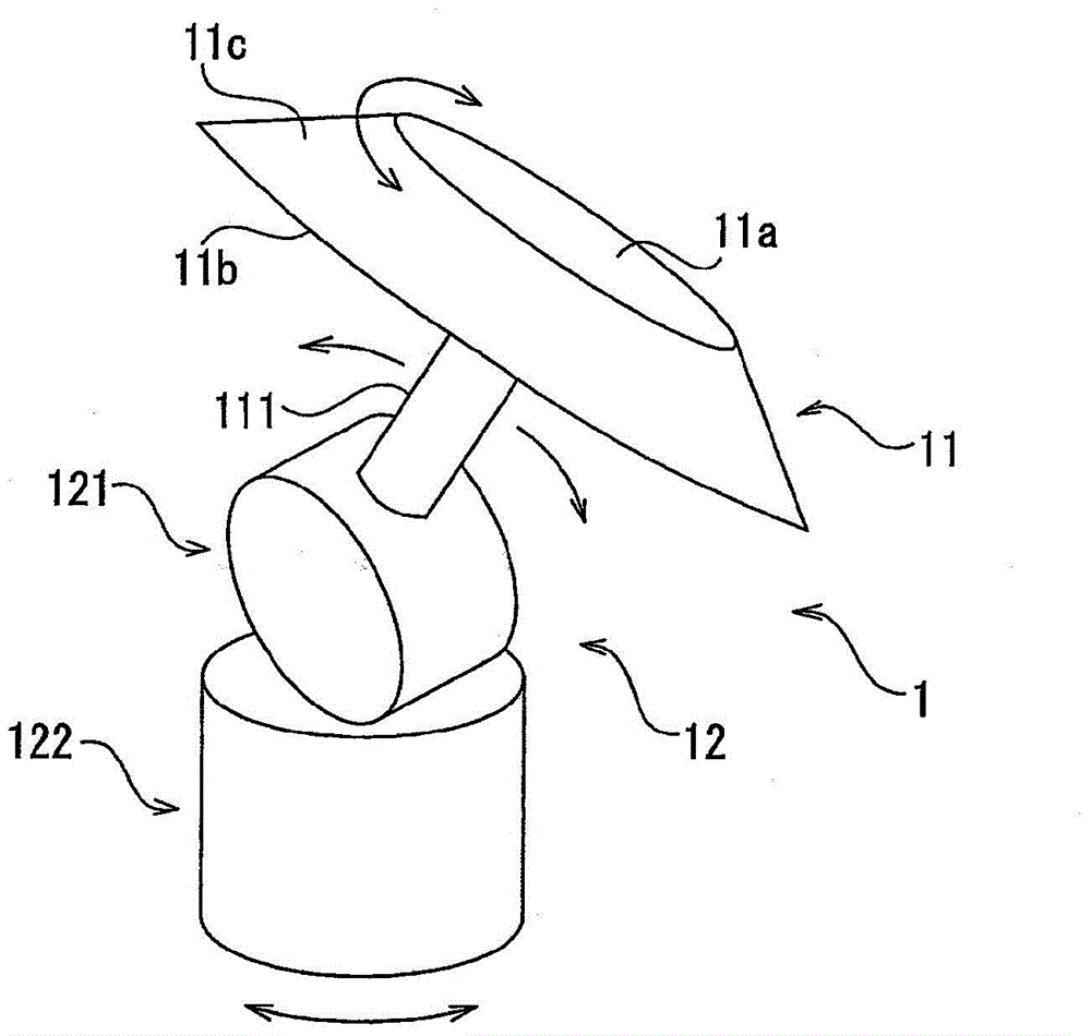
[0048] (1) The rotary table 11 can also be as Figure 7 The disc shape shown. At this time, the outer peripheral side of the disc serves as the mounting surface. If the rotary table 11 is in the shape of a disc, preferably, the pillars 31 are suspended from above, so that the rotary table 11 does not interfere with the pillars 31 of the roller conveyor 3 at the receiving position.

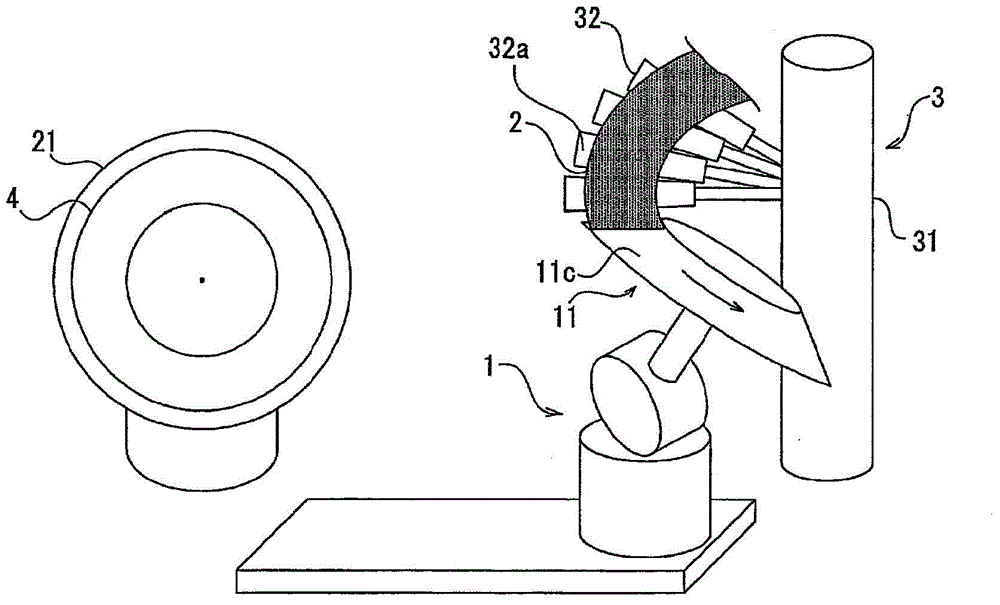
[0049] (2) In the above-mentioned embodiment, although the roller conveyor 3 was shown as an example of a supply apparatus, it is not limited to this. For example, it is also possible to directly supply the bent rubber member 2 by using an extruder capable of extruding the rubber member 2 in a bent state.

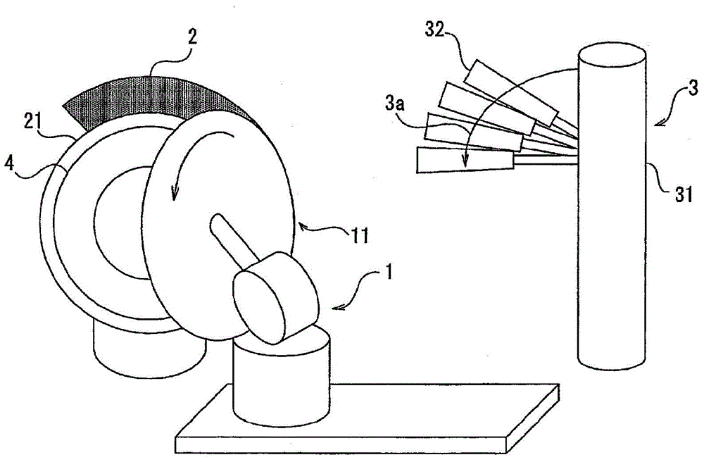
[0050] (3) Moreover, in the above-mentioned embodiment, the roller conveyor 3 which conveys the rubber member 2 from top to bottom was shown as an example of a supply apparatus. However, the roller conveyor 3 may convey the rubber member 2 from bottom to top.


PUM


Abstract

The object of the invention is to provide a conveying device which receives a curved rubber member supplied from a supply device and delivers the rubber member to a supply target device in a state of maintain the curvature. The conveying device (1) is a conveying device for receiving a curved rubber member (2) supplied by a roller type conveying machine (3) and delivering the rubber member to a forming roller (4). The conveying device includes a rotary table (11) having an annular mounting surface (11c) on which the curved rubber member (2) is placed, and a moving mechanism (12) capable of moving the rotary table (11) between a receiving position and a delivery position, wherein the rotary table (11) is rotated at the receiving position to roll up the rubber member, is moved from the receiving position to the delivery position, and is reversely rotated at the delivery position to roll back the rubber member (2).

Description

technical field [0001] The present invention relates to a conveying device for receiving a bent rubber member supplied from a supplying device and delivering it to a supplied device. Background technique [0002] In the manufacture of pneumatic tires, the following method is often used: when forming a ring-shaped filler strip, extrude the filler strip with a specified cross-sectional shape into a straight line, and wrap it around the outer peripheral side of the bead wire to make the gap between the ends Indirect engagement. However, when the bead wire is wound, tension is generated due to the gap between the inner and outer peripheral portions of the rubber filler, causing problems such as bending or thinning of the outer peripheral portion, peeling of the joint portion, or cutting of the rubber. [0003] In order to solve these problems, in Patent Document 1, the extruded linear filler strip is helically wound on a drum (drum) in such a manner that the inner diameter is s...

Claims


Application Information

Patent Timeline
Patent Type & Authority Applications(China)
IPC IPC(8): B29C31/00
CPCB29D30/48B29D2030/482
Inventor 宫本亮史坪谷壮祐
Owner TOYO TIRE & RUBBER CO LTD
Learn More