Airflow generating device and wind power generation system
A wind power generation system and airflow generation technology, applied in wind power generation, wind turbines, wind turbine combinations, etc., can solve problems such as insufficient response, difficulty in improving efficiency, and difficulty in maintaining power generation output stably, and achieve easy efficiency and stable power generation. output effect
- Summary
- Abstract
- Description
- Claims
- Application Information
AI Technical Summary
Problems solved by technology
Method used
Image

Examples
no. 1 Embodiment approach
[0027] [A] Whole structure of wind power generation system 1
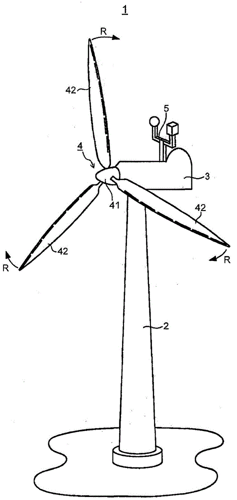
[0028] figure 1 It is a figure which shows the whole of the wind power generation system of 1st Embodiment.
[0029] Such as figure 1 As shown, the wind power generation system 1 is an upwind type propeller windmill and includes a tower 2 , a nacelle 3 , a rotor 4 , and a wind direction and speed measurement unit 5 .
[0030] Parts constituting the wind power generation system 1 will be described in order.
[0031] [A-1] Tower 2
[0032] The tower 2 extends in the vertical direction, and its lower end is fixed to a base (illustration omitted) embedded in the ground.
[0033] [A-2] Pod 3
[0034] The pod 3 is arranged on the upper end of the tower 2 .
[0035] The pod 3 is supported on the upper end portion of the tower 2 so as to be rotatable about a vertical axis in order to adjust a yaw angle.
[0036] [A-3] Rotor 4
[0037] The rotor 4 is rotatably supported by one end portion of the nacelle 3 , and rota...
no. 2 Embodiment approach
[0084] [A] structure etc.
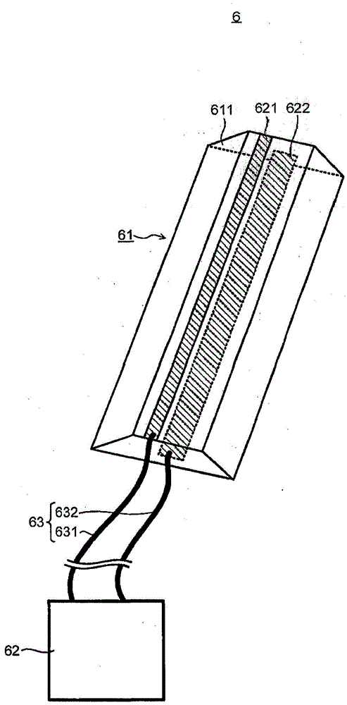
[0085] Figure 5 It is a figure which schematically shows the airflow generator 6 in the wind power generation system of 2nd Embodiment. exist Figure 5 in, with image 3Similarly, it shows that the main body 61 of the airflow generating device 6 is arranged on the windmill blade 42 (refer to figure 2 ) before the state, the main body portion 61 is shown in a perspective view.
[0086] In the second embodiment, if Figure 5 As shown, the main body portion 61 of the air flow generator 6 is different from that of the first embodiment. In the second embodiment, except for the above-mentioned differences and related points, descriptions of overlapping items such as the same configuration as those in the first embodiment are appropriately omitted.
[0087] Such as Figure 5 As shown, the air flow generating device 6 is the same as that of the first embodiment (refer to image 3 ) similarly includes a main body portion 61 , a voltage application ...
no. 3 Embodiment approach
[0101] [A] structure etc.
[0102] Figure 6 , Figure 7 It is a figure which shows the airflow generator 6 in the wind power generation system of 3rd Embodiment.
[0103] Figure 6 and image 3 Similarly, it shows that the main body 61 of the airflow generating device 6 is arranged on the windmill blade 42 (refer to figure 2 ) before the state, the main body portion 61 is shown in a perspective view.
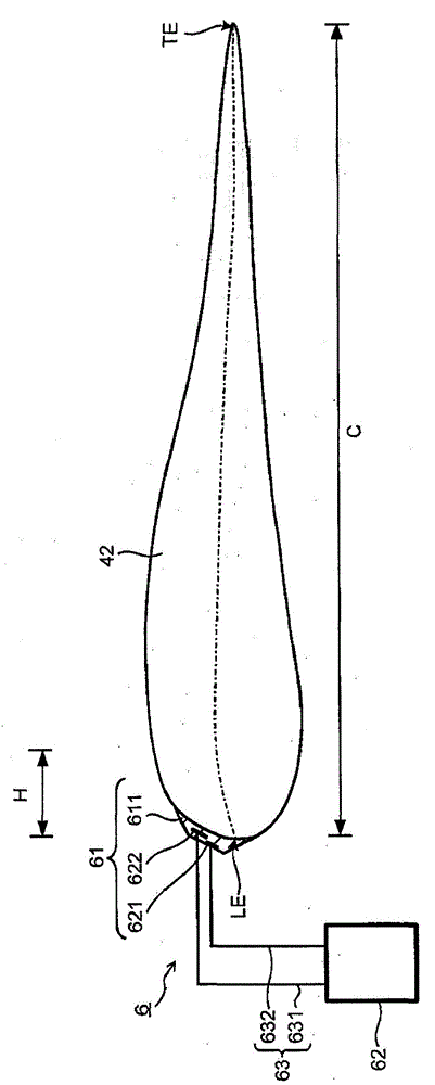
[0104] Figure 7 and Figure 4 Similarly, it is a figure which shows the main-body part 61 of the airflow generator 6. As shown in FIG. here, Figure 7 (a) is a sectional view, Figure 7 (b) is a plan view. Figure 7 (a) is equivalent to Figure 7 (b) The cross-section of the XX part.
[0105] In the third embodiment, if Figure 6 , Figure 7 As shown, the shape of the base body 611 of the main body portion 61 is different from that of the first embodiment. In addition, in the third embodiment, the connecting wire 71 is also provided in the base body 611 . In t...
PUM
 Abstract
Description
Claims
Application Information
 - R&D Engineer
- R&D Manager
- IP Professional
- Industry Leading Data Capabilities
- Powerful AI technology
- Patent DNA Extraction
Browse by: Latest US Patents, China's latest patents, Technical Efficacy Thesaurus, Application Domain, Technology Topic.
© 2024 PatSnap. All rights reserved.Legal|Privacy policy|Modern Slavery Act Transparency Statement|Sitemap