Solid oxide fuel cell

a fuel cell and solid oxide technology, applied in the field of solid oxide fuel cells, can solve the problems of slow gas g velocity, difficult reaction, and inability to generate electricity, and achieve the effect of simple structure and stably increasing power generation outpu

Inactive Publication Date: 2015-05-12
SHINKO ELECTRIC IND CO LTD
View PDF25 Cites 0 Cited by
  • Summary
  • Abstract
  • Description
  • Claims
  • Application Information

AI Technical Summary

Benefits of technology

[0046]The invention intends to form a fuel cell into a simple structure and to stably heighten the power generation output.
[0047]In the invention, a structure where electrodes of same kind are disposed faced to each other is adopted, a gap is disposed between both electrodes with the gas set within a predetermined range, a configuration where heat is contained is adopted, and thereby the power generation output is heightened.
[0070]Like a configuration of the invention, when in a fuel cell a plurality of cells is disposed faced to each other with a gap, in comparison with an existing battery, a very high power generation efficiency can be obtained. Furthermore, since a battery of the invention is very simple in the structure, can very rapidly generate electricity and is formed in a single chamber type, oxygen partial pressure at an anode electrode layer is high and a fuel is decomposed to CO and H; accordingly, there is no need of a device for fuel modification. Still furthermore, a fuel cell can be rapidly started up.

Problems solved by technology

As big problems of the modern world, an energy problem and an environmental problem can be cited.
When a substrate temperature of the solid oxide is low, since the internal resistance becomes larger to be difficult for the oxygen ion to move and for a reaction to occur, the electricity is not generated.
Accordingly, the diffusion velocity of the gas G is slow, a chemical reaction is difficult to occur, an internal diffusion overvoltage becomes larger, and thereby the power generation output is small.
In the existing technologies, since the anode electrode layer and the cathode electrode layer are laminated, there are irregularities in the flatness of a cell surface and the surface roughness of the electrode.
Such a management is very expensive and very dangerous.
As mentioned above, in the existing technology, there are problems in that the power generation output that can be extracted is small and the gas management has to be sufficiently applied.

Method used


Image

  • Solid oxide fuel cell
  • Solid oxide fuel cell
  • Solid oxide fuel cell

Examples


Embodiment Construction

[0077]In what follows, examples of the invention will be described.

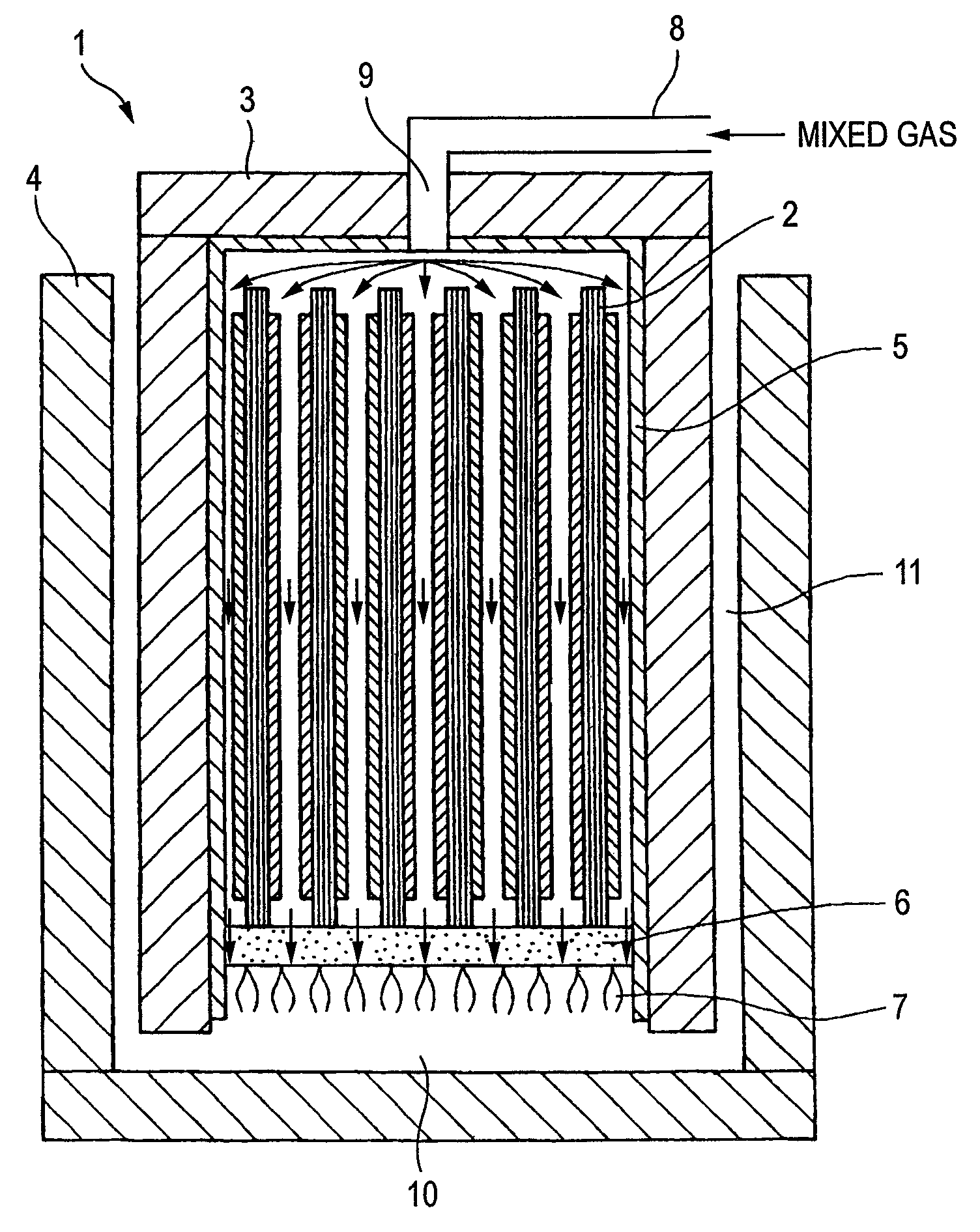
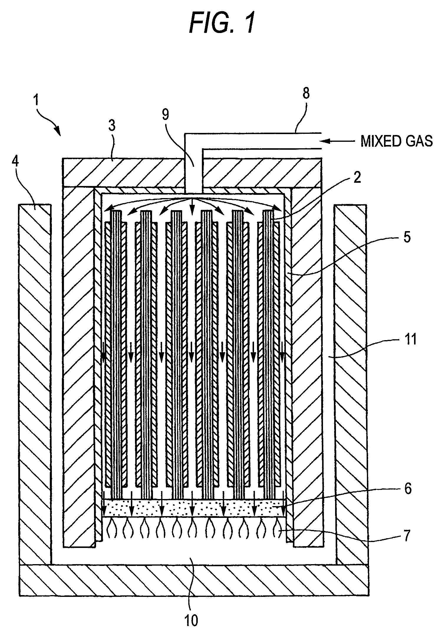
[0078]FIG. 1 is a sectional view of a solid oxide fuel cell of the invention. In the drawing, reference numerals 1 through 11, respectively, express a solid oxide fuel cell, a battery cell, an internal vessel, an external vessel, a highly conductive material layer, a porous body, a flame, an introduction pipe of a mixture gas of fuel and air, an inlet port, a bottom space formed by the porous body 6 and the external vessel 4 and a space between side surfaces formed from the internal vessel 3 and the external vessel 4.

[0079]In FIG. 1, the external vessel 4 and the internal vessel 3 of the fuel cell 1 is made of a heat-insulating material and between both the space 11 therefrom burnt exhaust gas is exhausted is disposed. Inside of the internal vessel 3, a plurality of oblong planar cells 2 is disposed and the porous body 6 that supports bottom portions of the plurality of cells 2 and allows a mixture gas G described be...


PUM

PropertyMeasurementUnit
conductiveaaaaaaaaaa
widthaaaaaaaaaa

Abstract

To an internal vessel that houses cells of a solid oxide fuel cell, an external vessel is further disposed. In the internal vessel, a plurality of planar cells is disposed vertically with a gap between the cells, a mixed gas of a fuel and air is descended from top down through the gap having a predetermined width between the cells, and, at a bottom portion of the housing space, the mixed gas is burned to generate electricity.

Description

BACKGROUND OF THE INVENTION[0001]The invention relates to a solid oxide fuel cell, in particular, a solid oxide fuel cell that is simple in a structure, can generate electricity at a high density, and is easy to handle.[0002]As big problems of the modern world, an energy problem and an environmental problem can be cited. As one of technologies that contribute to overcome the problems, a fuel cell technology is expected and various studies are in progress to achieve higher efficiency and low cost thereof.[0003]The fuel cells are categorized in four types depending on kinds of electrolytes that constitute a battery. That is, 1) a solid polymer type where an electrolyte is a polymer exchange membrane, 2) a phosphoric acid type where an electrolyte is phosphoric acid, 3) a molten carbonate type where an electrolyte is carbonate and 4) a solid oxide type where an electrolyte is a solid oxide can be cited.[0004]The invention relates to the fourth type thereof, that is, a solid oxide fuel ...

Claims


Application Information

Patent Timeline
Patent Type & Authority Patents(United States)
IPC IPC(8): H01M8/10H01M8/04H01M4/88H01M4/90H01M8/24
CPCH01M4/8885H01M8/2425H01M8/247H01M4/9016Y02E60/50H01M8/2432H01M8/2457H01M8/2484
Inventor HORIUCHI, MICHIOTOKUTAKE, YASUESUGANUMA, SHIGEAKIYOSHIIKE, JUNKATAGIRI, FUMIMASA
Owner SHINKO ELECTRIC IND CO LTD
Why Eureka
Try Eureka