A valve spring heat treatment furnace swing device

A heat treatment furnace and valve spring technology, applied in the field of springs, can solve the problems of uneven heating, influence of valve spring quality, time-consuming and labor-intensive, etc., and achieve the effect of improving product quality and saving manpower

Active Publication Date: 2016-07-20
安庆谢德尔汽车零部件有限公司
View PDF5 Cites 1 Cited by
  • Summary
  • Abstract
  • Description
  • Claims
  • Application Information

AI Technical Summary

Problems solved by technology

Therefore, when the valve spring is heat treated, the quality of the valve spring will be affected due to uneven heating.
At present, manual operation is used to prevent the valve spring from accumulating at the entrance of the heat treatment furnace, but this method is time-consuming and laborious, and it is easy to cause operational errors to affect the quality of the valve spring

Method used


Image

  • A valve spring heat treatment furnace swing device
  • A valve spring heat treatment furnace swing device

Examples


Embodiment Construction

[0013] The present invention will be further described below in conjunction with accompanying drawing:

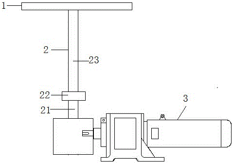
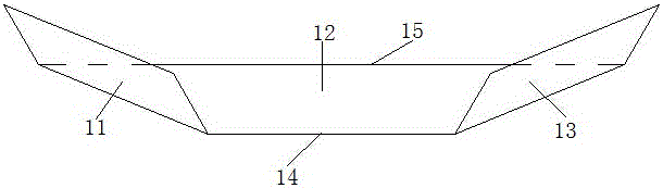
[0014] like Figure 1-Figure 2 The oscillating device shown in the valve spring heat treatment furnace includes an oscillating head 1 for changing the conveying direction of the valve spring, a transmission mechanism 2 and a geared motor 3 for changing the oscillating direction of the oscillating head. The input end 14 of the swing head 1 for changing the delivery direction of the valve spring is connected to the output end of the conveyor, and the output end 15 is connected to the input end of the heat treatment furnace. Preferably, the height of the input end 14 of the swing head for changing the delivery direction of the valve spring is higher than the height of the output end 15 thereof. The output end of the transmission mechanism 2 for changing the swinging direction of the swinging head is fixedly installed under the swinging head 1 . The output shaft of the reduct...


PUM


Abstract

The invention relates to an oscillating device for a valve spring heat treatment furnace, which comprises an oscillating head for changing the delivery direction of the valve spring, a transmission mechanism for changing the oscillating direction of the oscillating head, and a deceleration motor. The input end of the swing head for changing the delivery direction of the valve spring is connected with the output end of the conveyor, and the output end is connected with the input end of the heat treatment furnace. The height of the input of the swing head for changing the delivery direction of the valve spring is higher than the height of its output. The output end of the transmission mechanism for changing the swinging direction of the swinging head is fixedly installed under the swinging head. The output shaft of the reduction motor is fixedly connected with the input end of the transmission mechanism for changing the swing direction of the swing head. The invention can quickly and continuously change the conveying direction of the valve spring, avoiding its accumulation at the entrance of the heat treatment furnace, thereby saving manpower and material resources and improving the quality of the valve spring.

Description

technical field [0001] The invention relates to the technical field of springs, in particular to an oscillating device for a valve spring heat treatment furnace. Background technique [0002] During the production and processing of valve springs, the valve springs are conveyed by conveyors to the entrance of the heat treatment furnace. However, since the furnace width of the heat treatment furnace is wider than that of the conveyor, after the valve spring reaches the heat treatment furnace from the conveyor, it will accumulate at the entrance of the heat treatment furnace. Therefore, when the valve spring is heat treated, the quality of the valve spring will be affected due to uneven heating. At present, manual operation is used to prevent the valve springs from accumulating at the entrance of the heat treatment furnace, but this method is time-consuming and laborious, and operation errors are likely to affect the quality of the valve springs. Contents of the invention ...

Claims


Application Information

Patent Timeline
Patent Type & Authority Patents(China)
IPC IPC(8): B65G69/04
Inventor 段建徐军石有虎王军曾凡程锐陈国富王伟陈平安徐亚军
Owner 安庆谢德尔汽车零部件有限公司
Why Eureka
Try Eureka