

Water-bearing rock stratum borehole wall structure and construction method
A construction method and shaft wall technology, applied in shaft equipment, earthwork drilling, shaft lining, etc., can solve the problems of unused surrounding rock mass bearing capacity, peeling, accumulation, etc., to improve compactness and bond strength, reduce Project cost and the effect of thinning the well wall
- Summary
- Abstract
- Description
- Claims
- Application Information
AI Technical Summary
Problems solved by technology
Method used
Image

Examples
Embodiment 1
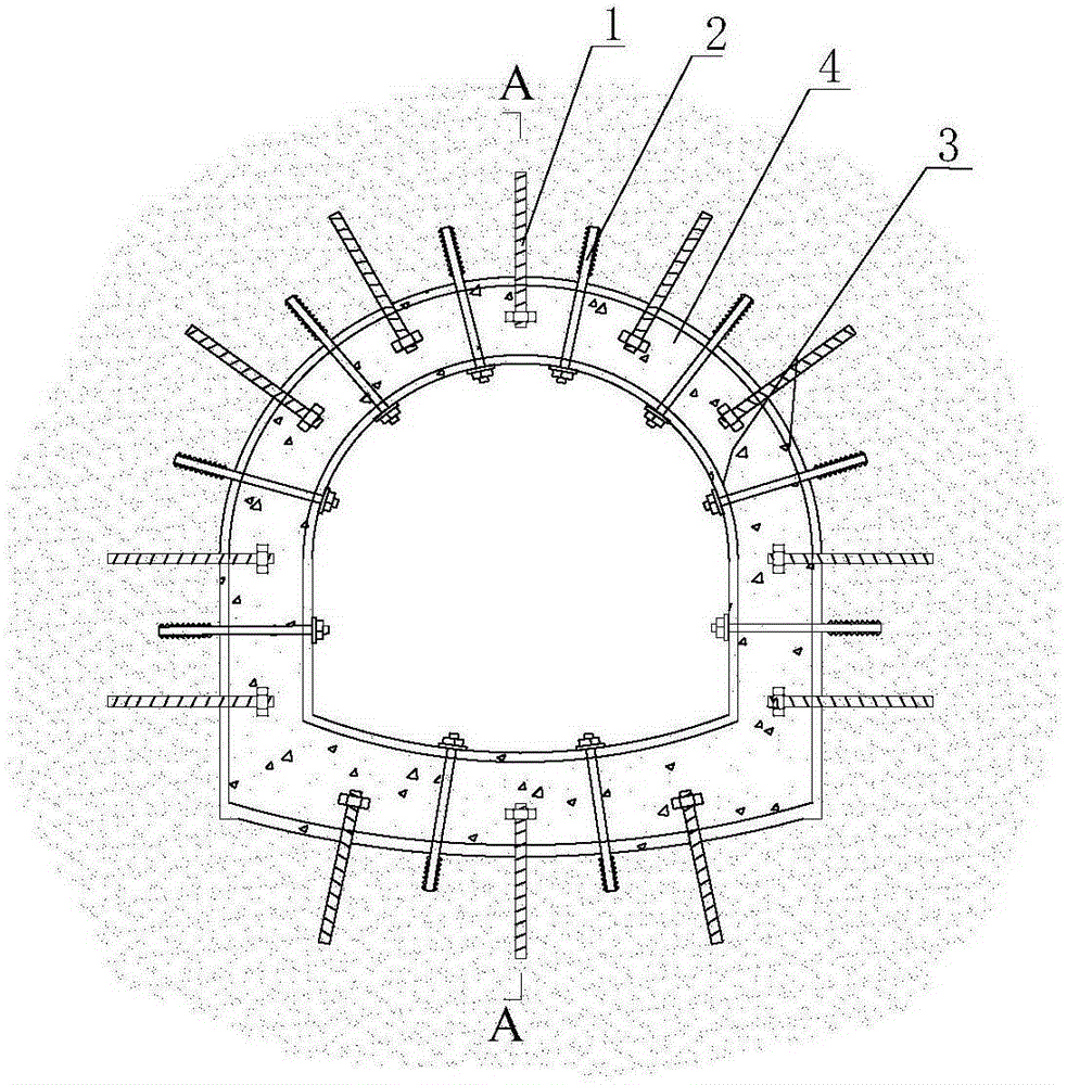
[0046] Example 1: The bottom plate is an inclined shaft wall structure with an inverted arch type
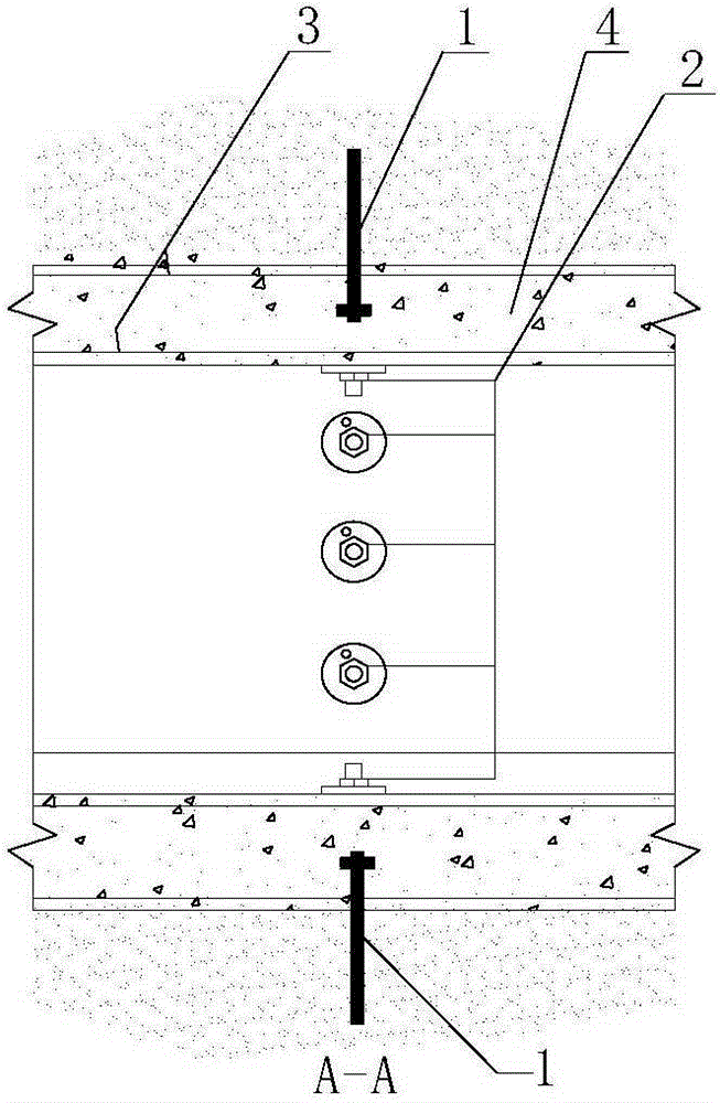
[0047] The bottom plate of the present invention is a flat inclined shaft wall structure, which is composed of anchor rod I1, anchor rod II2, steel skeleton 3, and concrete 4 (see Picture 1-1 , Figure 1-2 ).
[0048] Specific construction steps:
[0049] (1) After the wellbore of the inclined shaft in the aquifer is excavated, firstly, according to a certain axial and circumferential distance, drill holes in the surrounding rock mass and install the anchor rods I1 and II2; the outer end of the anchor rod I1 extends into the inside of the well wall 4 Instead of penetrating the shaft wall, the outer end of the anchor rod II2 penetrates the shaft wall concrete 4 just to reach its inner surface;
[0050] (2) Carry out the binding construction of the shaft wall steel skeleton 3, and firmly connect with the anchor rods I1 and II2 to form a three-dimensional steel skeleton, and con...
Embodiment 2
[0055] Embodiment 2: the bottom plate is a straight type inclined shaft wall structure;
[0056] The bottom plate of the present invention is a flat inclined shaft wall structure, which is composed of anchor rod I1, anchor rod II2, steel skeleton 3, and concrete 4 (see diagram 2-1 , Figure 2-2 ).
[0057] Others are the same as in Example 1.
Embodiment 3
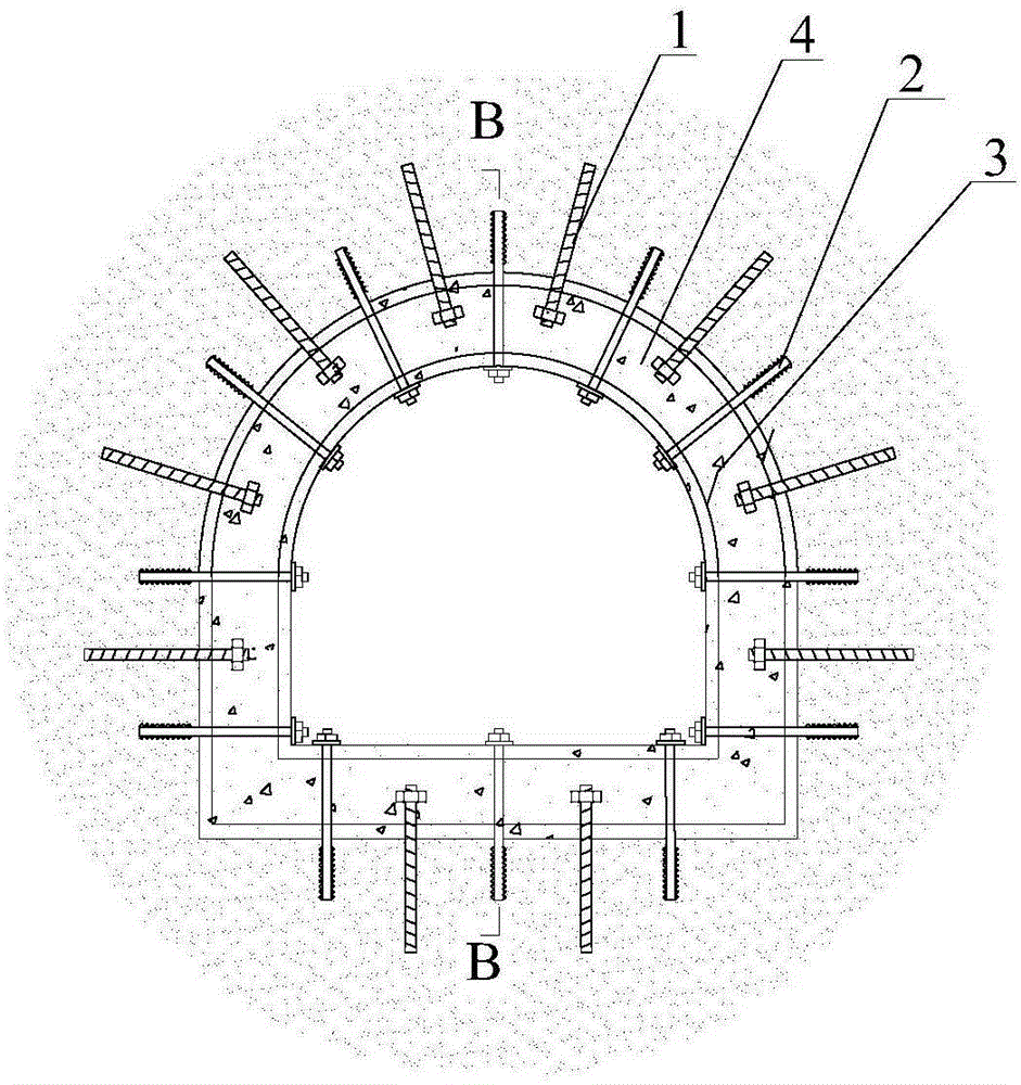
[0058] Embodiment 3: shaft wall structure;
[0059] The shaft wall structure of the present invention is composed of anchor rod I1, anchor rod II2, steel skeleton 3, and concrete 4 (see Figure 3-1 , Figure 3-2 ).
[0060] Others are the same as in Example 1.
PUM
 Abstract
Description
Claims
Application Information