
A Thermal Fault Detection System for Transmission Transformer

A fault detection and transformer technology, applied in the field of power transmission, can solve problems such as the influence of thermal fault diagnosis of solid insulation

Inactive Publication Date: 2017-02-22
杭州市电力设计院有限公司
View PDF3 Cites 0 Cited by
  • Summary
  • Abstract
  • Description
  • Claims
  • Application Information

AI Technical Summary

Problems solved by technology

[0009] Of course, the three-ratio method also has obvious shortcomings when judging thermal faults of transformers. For example, it can be found from the analysis of the gas production mechanism that when the content of each gas component and the gas production rate do not exceed the standard, the transformer is in normal operation. , the three-ratio method diagnosis is invalid, only when the gas content exceeds the standard or the gas production rate exceeds the standard, or there is sufficient basis to determine that the transformer is faulty, the three-ratio method diagnosis will be meaningful
[0010] Also, when the transformer fault involves the decomposition of solid insulating materials, a large amount of carbon dioxide (CO2) and carbon monoxide (CO) will be generated, but the three-ratio method recommended by the guidelines does not refer to carbon dioxide (CO2) and carbon monoxide (CO) information, so this has a great impact on the diagnosis of thermal faults of solid insulation
[0011] Therefore, in order to overcome the above defects, it is necessary to improve the three-ratio method currently used to improve the accuracy and stability of diagnosing thermal faults of power transformers, and at the same time avoid misjudgment operations or other factors that have adverse effects

Method used


Image

  • A Thermal Fault Detection System for Transmission Transformer
  • A Thermal Fault Detection System for Transmission Transformer
  • A Thermal Fault Detection System for Transmission Transformer

Examples


Embodiment Construction

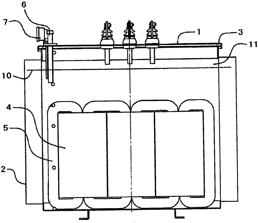
[0024] Such as figure 1 As shown, the present invention discloses an oil-immersed power transmission transformer, and the structure diagram of the oil-immersed power transmission transformer is shown in figure 1 As shown, the transformer includes a transformer casing 1 covering the entire transformer, an insulating oil tank 2 connected to the transformer casing 1, a transformer gasket 3, a main functional part of a power transmission transformer, a winding coil 4 and an iron core 5, and a detection device 6 And the thermometer 7 is located at the upper edge of the transformer housing 1 for detection of relevant control data, the insulating oil 10 and the air layer 11 in the insulating oil tank 2 .

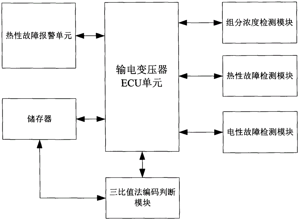
[0025] Such as figure 2As shown, the transmission transformer thermal fault detection system of the present invention includes a transmission transformer ECU unit, a storage unit, a component concentration detection module, a thermal fault detection module, an electrical fault de...


PUM


Abstract

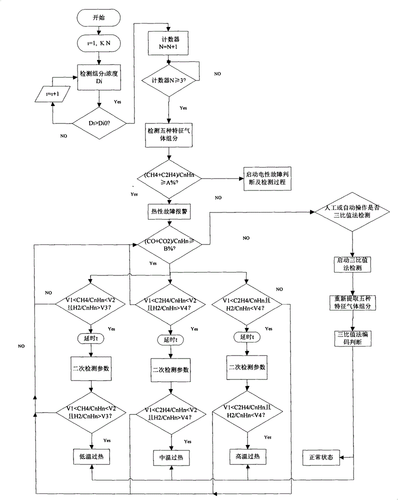
The invention provides a thermal fault detecting system for a power transmission transformer. The emphasis is that thermal faults are monitored, the thermal fault detecting system for the power transmission transformer can judge the thermal faults in advance before detection is performed through a three-ratio method,, if the faults are judged to be the thermal faults, gas component detection is carried out in advance, if solid insulating material decomposition is not involved, the three-ratio method continues to be used for detection, and if solid insulating material decomposition is involved in monitoring, a secondary detection and judgment method is selected for detection. In this way, inaccurate or unstable measurement caused by the influence of multiple factors can be avoided to the maximum extent, the detection effect of the three-ratio method is better, and the influence on diagnosis by carbon dioxide (CO2) and carbon monoxide (CO) generated by solid insulation faults is avoided.

Description

technical field [0001] The invention relates to a thermal fault detection system of a power transmission transformer, which belongs to the technical field of power transmission. Background technique [0002] Due to the excellent heat dissipation and insulation properties of transformer oil, oil-immersed power transformers are widely used in power systems. During normal operation, the transformer will slowly age under the influence of mechanical stress, heat, electricity and other factors, and generate some flammable gases. If there is an internal latent fault in the transformer, the energy released from the faulty part will accelerate the cracking of the insulating material, which will greatly increase the content of dissolved gas in the oil and the rate of gas production. By obtaining transformer oil samples, gas chromatography can be used to obtain the content of each component of dissolved gas in the oil, so as to evaluate the health of the transformer or analyze the fai...

Claims


Application Information

Patent Timeline
Patent Type & Authority Patents(China)
IPC IPC(8): G01R31/00
Inventor 俞容江胡晨刚李家栓马炯
Owner 杭州市电力设计院有限公司
Learn More