System and method for assessing retinal functionality and optical stimulator for use therein

一种视网膜、视觉系统的技术,应用在光刺激器,电生理学和精神物理学的应用领域

Inactive Publication Date: 2014-10-01
ANNIDIS
View PDF9 Cites 12 Cited by
  • Summary
  • Abstract
  • Description
  • Claims
  • Application Information

AI Technical Summary

Problems solved by technology

The luminosity of the screen is also an issue and in some cases can limit experiments / assessments that require greater luminosity, i.e. faster flashes or brighter stimulus images

Method used


Image

  • System and method for assessing retinal functionality and optical stimulator for use therein
  • System and method for assessing retinal functionality and optical stimulator for use therein
  • System and method for assessing retinal functionality and optical stimulator for use therein

Examples


Embodiment Construction

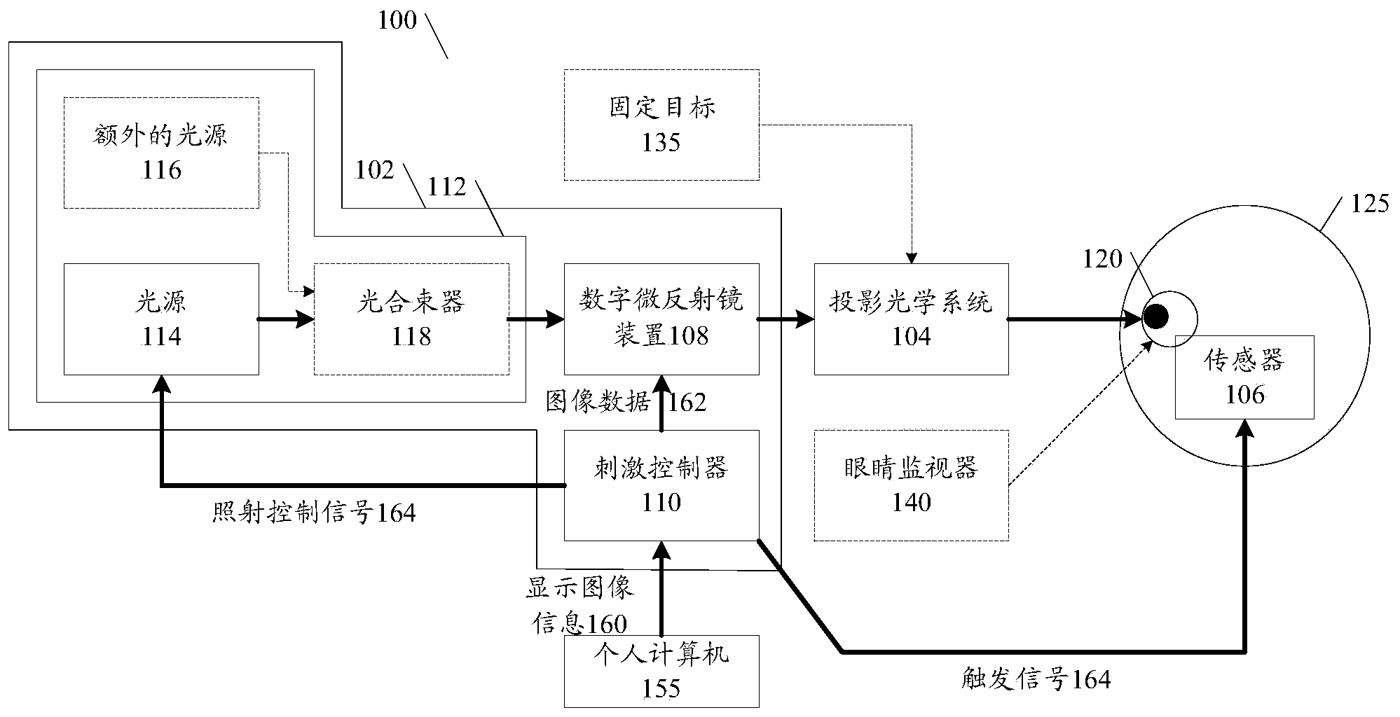
[0066] figure 1 A specific embodiment of a system 100 for assessing retinal function is illustrated. The system 100 includes a photostimulator 102 for generating one or more stimulus images of input light, a projection optics system 104 for projecting the imaging of the photostimulation images onto the retina of an eye 120 of a subject 125, and sensing stimulus imaging causes The response of the sensing unit 106 .

[0067] As shown, the optical stimulator 102 includes a DMD device 108 with micromirror arrays (not shown), which can be individually switched in response to control signals from a controller 110 . The input light for the diffuse micromirror is provided by a light input unit 112 comprising a light source 114 , such as an LED, coupled to the DMD device 108 . Optionally, the light input unit 112 may include one or more additional light sources for emitting light having a different wavelength than the light emitted by the light source 114 . exist figure 1 In , th...


PUM


Abstract

A system and method for assessing the functionality of a visual system of the eye using a digital micro-mirror device (DMD) to generate a coded pattern which is illuminated by a light source. Optics project an image of the coded pattern onto the retina of the eye. Sensors detect electrical signals based on the response of the visual system to the image. One or more processors control the DMD and correlate the electrical response from the sensor with the coded DMD pattern to assess the functionality of the visual system.

Description

[0001] Cross References to Related Applications [0002] This application is related to and claims priority from US Provisional Patent Application No. 61 / 535,693 filed September 16, 2011, the entire contents of which are incorporated herein by reference. technical field [0003] The present invention relates to systems and methods for assessing the function of the retina and its associated parts of the visual system using a light stimulation device, and finds applications in the fields of medicine and clinical research, especially electrophysiology and psychophysics. The invention also relates to photostimulators utilized in such systems and methods. Background technique [0004] Photostimulators are widely used to generate illuminated images that illuminate the retina of a subject. For convenience of description, in this specification, the term "photostimulator" is used to include stimulators that emit visible light and / or invisible light. A subject's response to a stimu...

Claims


Application Information

Patent Timeline
Patent Type & Authority Applications(China)
IPC IPC(8): A61B3/10A61B3/12
CPCA61B3/0041A61B2576/02A61B3/0008A61B5/04842A61B3/12A61B5/378
Inventor 艾伦·博奥特杰里米·劳埃德·格里本
Owner ANNIDIS
Why Eureka
Try Eureka