Combined type thread self-locking hydraulic oil cylinder

A hydraulic cylinder and composite technology, applied in the direction of fluid pressure actuation device, etc., can solve the problems of poor locking reliability, low output force of hydraulic cylinder, high precision requirements of hydraulic valve, etc., and achieve high output force, output force improvement, locking The effect of high reliability

Inactive Publication Date: 2014-10-08
SHANGHAI HORIZON EQUIP ENG
View PDF5 Cites 7 Cited by
  • Summary
  • Abstract
  • Description
  • Claims
  • Application Information

AI Technical Summary

Problems solved by technology

However, this method of using a hydraulic valve to lock the hydraulic cylinder has high requirements on the accuracy of the hydraulic valve, and there is internal interference in the spool of the hydraulic valve, so it is impossible to achieve absolute locking of the hydraulic cylinder, and there is a defect of poor locking reliability.
[0004] In addition, the output force of existing hydraulic cylinders is relatively low. In some working conditions that require high output force (such as civil foundation pit construction), multiple hydraulic cylinders are often required to cooperate with each other to output power at the same time. Therefore, the existing hydraulic cylinders The output power still needs to be improved

Method used


Image

  • Combined type thread self-locking hydraulic oil cylinder

Examples


Embodiment Construction

[0014] The embodiments of the present invention will be described in further detail below in conjunction with the accompanying drawings, but the present embodiments are not intended to limit the present invention, and any similar structures and similar changes of the present invention should be included in the protection scope of the present invention.

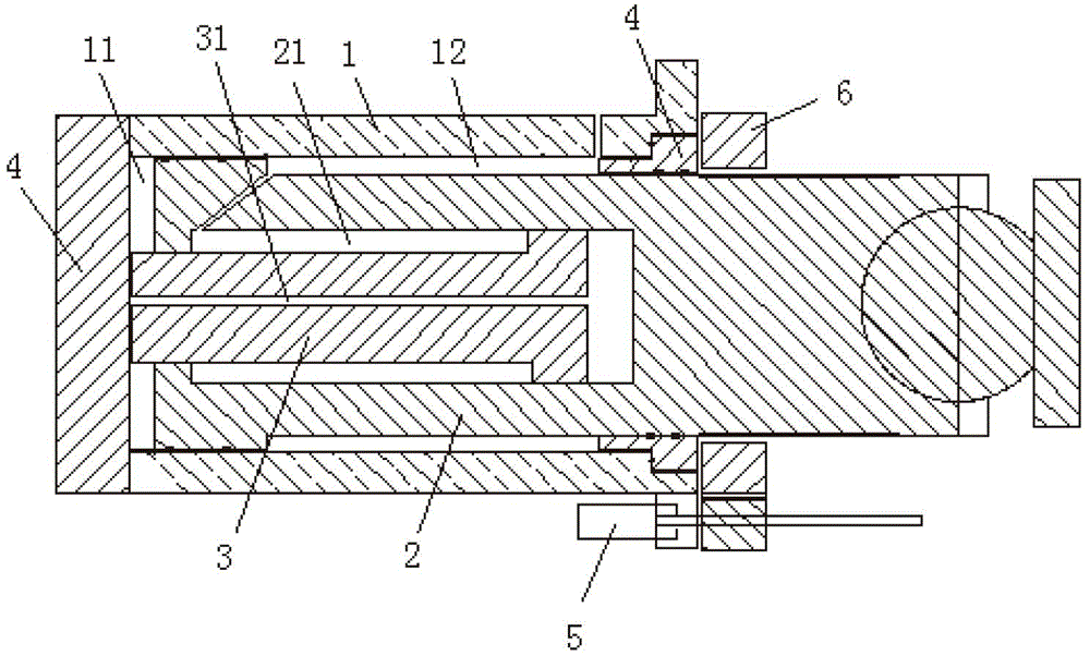
[0015] Such as figure 1 As shown, a compound threaded self-locking hydraulic cylinder provided by the embodiment of the present invention includes a cylinder 1 and a piston, and the left and right ends of the cylinder 1 are respectively closed by a cylinder head 4, which is characterized in that: There are two pistons, one of which is the main piston 2, and the other piston is the auxiliary piston 3;

[0016] The main piston 2 is installed in the inner cavity of the cylinder 1 in a sliding fit manner, and divides the inner cavity of the cylinder 1 into two independent sub-cavities on the left and right sides, wherein the left ...


PUM


Abstract

The invention relates to the technical field of hydraulic power equipment, in particular to a combined type thread self-locking hydraulic air cylinder. The technical problem that an existing oil cylinder is poor in locking reliability and low in output force is solved. The oil cylinder comprises a cylinder barrel, a main piston and an auxiliary piston. The main piston is arranged in an inner cavity of the cylinder barrel, the right end of the main piston stretches out of the cylinder barrel, and external threads with the central axis of the main piston as the spiral axis are formed on the right circumferential face of the main piston. A driving motor and an annular gear are arranged on the cylinder barrel, a power output shaft of the driving motor is meshed with the annular gear, and the annular gear is meshed with external threads on the right portion of the main piston through internal threads of an inner ring. The main piston is provided with an auxiliary cavity, the auxiliary piston is arranged in the auxiliary cavity and divides the auxiliary cavity into a left sub-cavity and a right sub-cavity, the left end of the auxiliary piston penetrates through the left end cavity wall of the auxiliary cavity to stretch into a rodless cavity, and the right sub-cavity of the auxiliary cavity is communicated with the rodless cavity of the cylinder barrel through a shaft hole formed in the auxiliary piston. The oil cylinder can achieve reliable locking and is high in output force.

Description

technical field [0001] The invention relates to the technology of hydraulic power equipment, in particular to the technology of a composite threaded self-locking hydraulic oil cylinder. Background technique [0002] The hydraulic cylinder is a device driven by hydraulic pressure to output power. It is mainly composed of a cylinder and a piston. The inner cavity of the cylinder is closed as a whole, and the piston is installed in the inner cavity of the cylinder in a sliding fit. working cavity. When the hydraulic cylinder is working, one of the working chambers enters the oil, and the other works to return the oil, which can push the piston to slide and output power. [0003] When the hydraulic cylinder is working, in order to ensure the safety of the hydraulic cylinder, it is usually necessary to configure a hydraulic valve on the inlet and outlet hydraulic lines of the hydraulic cylinder to lock the hydraulic cylinder to ensure that the hydraulic cylinder will not be unst...

Claims


Application Information

Patent Timeline
Patent Type & Authority Applications(China)
IPC IPC(8): F15B15/26F15B15/16
Inventor 冯琪权江辉李斌裴国金
Owner SHANGHAI HORIZON EQUIP ENG
Why Eureka
Try Eureka