Automatic sizing and cold shearing method and automatic sizing and cold shearing device

A fixed-length, automatic technology, applied in the field of automation, can solve the problems of busy button production operations, dangers, hidden safety hazards, etc., and achieve the effects of improving fault recovery capabilities, improving work and production efficiency, and ensuring normal production

Active Publication Date: 2014-10-15
BEIJING BESTPOWER INTELCONTROL TECH CO LTD
View PDF8 Cites 7 Cited by
  • Summary
  • Abstract
  • Description
  • Claims
  • Application Information

AI Technical Summary

Problems solved by technology

[0003] In the previous cut-to-length process, the positioning of the steel and the actions of the cold-shear nip roller, the cold-shear trim baffle, the cold-shear clutch, and the swing roller were all done manually. A kind of equipment is designed with corresponding buttons on the operati

Method used


Image

  • Automatic sizing and cold shearing method and automatic sizing and cold shearing device
  • Automatic sizing and cold shearing method and automatic sizing and cold shearing device
  • Automatic sizing and cold shearing method and automatic sizing and cold shearing device

Examples


Embodiment 1

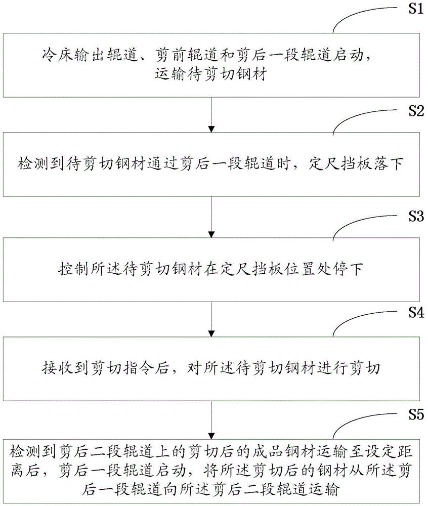
[0043] The invention provides an automatic cut-to-length cold shearing method, please refer to figure 1 As shown, it is the first embodiment of an automatic cut-to-length cold shearing method of the present invention, including:

[0044] Step S1, the cooling bed output roller table, the pre-cut roller table and the post-cut roller table start to transport the steel to be cut;

[0045] Step S2, when it is detected that the steel to be cut passes through a section of the roller table after the cut, the fixed-length baffle falls;

[0046] When the fourth area sensor detects that the steel to be cut passes, the fixed-length baffle falls and enters the automatic positioning program for fixed-length shearing; when the fourth area sensor does not detect that the steel to be cut passes, the fixed-length baffle is in the up position. Up state

[0047] Step S3, controlling the steel to be cut to stop at the position of the fixed-length baffle;

[0048] Step S4, after receiving the cutting instru...

Embodiment 3

[0078] The third embodiment achieves the above-mentioned effect, and it cannot guarantee that the said group of steel materials are aligned. This will make the steel materials obtained by the first shearing different in length, and therefore cannot guarantee that the finished steel materials are qualified.

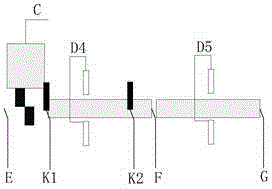
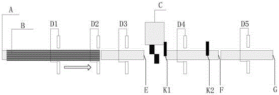
[0079] See Figure 4 As shown, it is a structural diagram of Embodiment 4 of an automatic cut-to-length cold shearing system of the present invention. It is provided in this embodiment. The system of the present invention may also include a cooling bed output roller table A; ; Cut the front roller table E; the third area sensor D3; the first area sensor D1, the second area sensor D2.

[0080] The cooling bed output roller table A is used to receive the steel material B to be cut from the cooling bed and transmit the steel material B to be cut; the first area sensor D1 is located in the middle of the cooling bed output roller table and is used to detect whether The steel to be ...


PUM


Abstract

The invention relates to an automatic sizing and cold shearing method and an automatic sizing and cold shearing device. The method includes: starting a cold bed output roller table, a pre-shearing roller table and a first after-shearing roller table to transport to-be-sheared steel; enabling a sizing baffle to fall down when the fact that the to-be-sheared steel passes through the first after-shearing roller table is detected; controlling the to-be-sheared steel to stop at the position of the sizing baffle; shearing the to-be-sheared steel when a shearing order is received; lifting the sizing baffle; after sheared finished steel products on a second after-shearing roller table are transported to a set distance, starting the first after-shearing roller table to transport the sheared steel from the first after-shearing roller table to the second after-shearing roller table. The steel on the roller tables is positioned by area sensors, and positioning parameters can be set and adjusted on a picture. Buttons, needed to be operated in actual production, of an operation table are greatly reduced, and consequently working and production efficiency can be improved.

Description

Technical field [0001] The invention relates to the field of automation, in particular to an automatic cut-to-length cold shearing method and a device thereof. Background technique [0002] In the steel production process, there are a set of important shearing equipment in the cooling bed area, cold shear and sizing machine. The main function of these equipments is to cut the steel on the cooling bed to a certain length, and the length of the steel after the cut meets the specifications of the finished product. [0003] In the past cut-to-length cutting process, the positioning of the steel and the cold-cut nip roller, cold-cut head baffle, cold-cut clutch, and swing roller were all done manually. A kind of equipment is designed with corresponding buttons on the operating table, because too many buttons are involved, the production operation is rushed. The cold shearing machine includes several pneumatic or hydraulic equipment, which has certain safety hazards. If there are too m...

Claims


Application Information

Patent Timeline
IPC IPC(8): B23D33/00
Inventor 杨志惠秦川李鹏飞
Owner BEIJING BESTPOWER INTELCONTROL TECH CO LTD
Why Eureka
Try Eureka