Machining method and machining apparatus

Active Publication Date: 2006-10-31
HITACHI SEIKO LTD
View PDF9 Cites 2 Cited by
  • Summary
  • Abstract
  • Description
  • Claims
  • Application Information

AI Technical Summary

Benefits of technology

[0019]In order to solve the foregoing problem belonging to the related art, it is an object of the invention to provide a machining method and a ma

Problems solved by technology

When such measurement is carried out, improvement in machinin

Method used


Image

  • Machining method and machining apparatus
  • Machining method and machining apparatus
  • Machining method and machining apparatus

Examples


embodiment 2

Machining Accuracy is Required

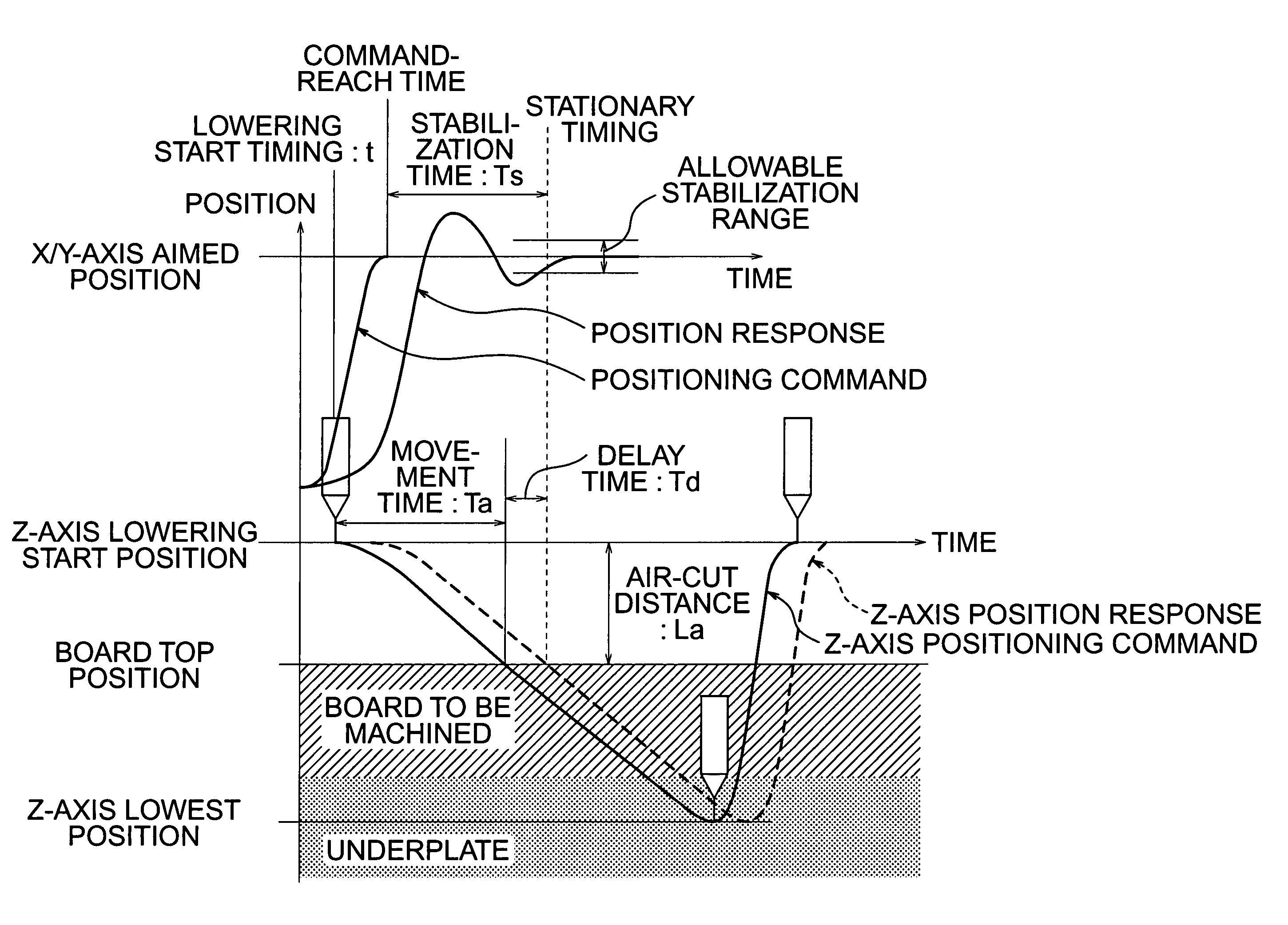
[0064]When high machining accuracy is required, the allowable stabilization range is narrowed in advance as shown by the solid line in FIG. 6. Then, the stabilization time Ts is observed in this state. Thus, the machining productivity can be improved while the machining accuracy is improved.

[0065]On the contrary, when the machining accuracy is not required that high, the allowable stabilization range is widened in advance as shown by the broken line in FIG. 6. Thus, the machining productivity can be improved.

[0066]Conventionally, the time for the drill 4 to escape from the board has not been taken into consideration. However, when the X-axis drive unit 3 and the Y-axis drive unit 7 are operated as soon as the drill 4 escapes from the board, the machining productivity can be improved.

[0067]In this embodiment, when the stabilization time Ts calculated in Step 2 and the magnitude of overshoot or undershoot of the response waveform are out of their predeter...


PUM

PropertyMeasurementUnit
Timeaaaaaaaaaa
Distanceaaaaaaaaaa
Stiffnessaaaaaaaaaa

Abstract

In a machining method and a machining apparatus, prior to machining, an NC control unit makes an X-axis drive unit move a table based on examination conditions specified in advance. Thus, the NC control unit obtains a stabilization time required from the command-reach time of a poisoning command and till the stabilization of position response of the table within a predetermined allowable range. Likewise, for moving a drill in a Y-axis direction, the NC control unit obtains a stabilization time required till the stabilization of position response within a predetermined allowable range. At the time of machining, the drill is moved in a Z-axis direction to cut into a printed wiring board as soon as the obtained stabilization time has passed.

Description

BACKGROUND OF THE INVENTION[0001]1. Field of the Invention[0002]The present invention relates to a machining method and a machining apparatus in which a table mounted with a work and a main shaft holding a tool are moved relatively to each other in X-, Y- and Z-directions perpendicular to one another for machining the work with the tool.[0003]2. Description of the Related Art[0004]FIG. 8 is a configuration diagram of a printed wiring board machining apparatus used conventionally. In FIG. 8, a printed wiring board 1 is fixed to the top of a table 2 with an underplate 9. The table 2 can be moved desirably in the front / rear (X) direction by an X-axis drive unit 3. A spindle 5 holding a drill 4 can be moved desirably in the up / down (Z) direction by a Z-axis drive unit 6. The Z-axis drive unit 6 can be moved desirably in the left / right (Y) direction by a Y-axis drive unit 7. Each of the X-, Y- and Z-axis drive units 3, 7 and 6 has a not-shown position detector, so that the drive unit can...

Claims


Application Information

Patent Timeline
IPC IPC(8): G06F19/00B23Q15/24B23B39/08B23B41/00B23Q17/22G05B19/402H05K3/00
CPCB23Q17/2233G05B19/402H05K3/0008G05B2219/41192Y10T29/49778H05K3/0047H05K2203/163G05B2219/45035
Inventor WATANABE, KAZUOYAMASHITA, TAKAHIKOITO, YASUSHINAGASAWA, KATSUHIRO
Owner HITACHI SEIKO LTD
Why Eureka
Try Eureka