
Double lock head control mechanism

A technology of control mechanism and lock head, applied in the direction of building lock, building structure, construction, etc., can solve the problem of blocking the passage of the deadbolt plate and so on.

Active Publication Date: 2017-03-01
WONLY SECURITY & PROTECTION TECH CO LTD
View PDF4 Cites 0 Cited by
  • Summary
  • Abstract
  • Description
  • Claims
  • Application Information

AI Technical Summary

Problems solved by technology

[0004] For this reason, the technical problem to be solved by the present invention is to overcome that when the toggle head of the double unlocking head of the prior art is used to toggle the deadbolt plate of the above-mentioned door lock locking device and moves along the direction of lock in and lock out, the toggle head will The problem of blocking the passage of the deadbolt plate, so as to provide a double unlocking head control mechanism that does not block the passage of the deadbolt plate of the above-mentioned door lock and locking device and is suitable for the above-mentioned door lock and locking device

Method used


Image

  • Double lock head control mechanism
  • Double lock head control mechanism
  • Double lock head control mechanism

Examples


Embodiment Construction

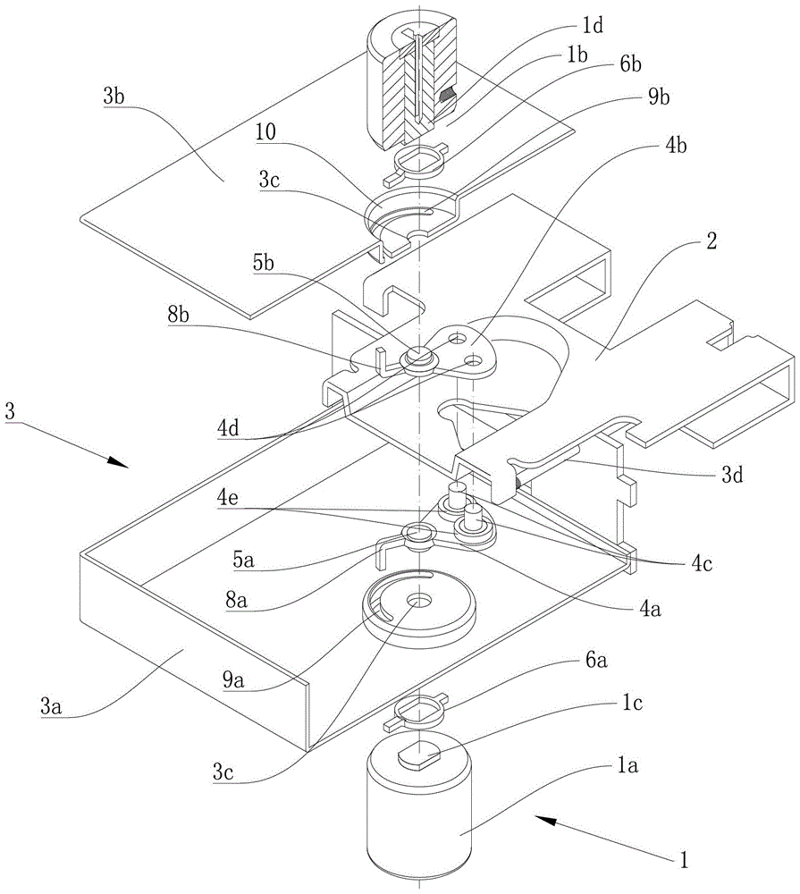
[0045] In the description of this application, the term "locked out" means the state where the deadbolt plate 2 is moved to the deadbolt housing 3 . The term "locked in" means that the bolt plate 2 moves to the state where the bolt is retracted into the lock case 3 . Correspondingly, the "locking out direction" refers to the moving direction of the locking bolt plate 2 during the locking out process. "Locking direction" refers to the moving direction of the locking bolt plate 2 during the locking process.

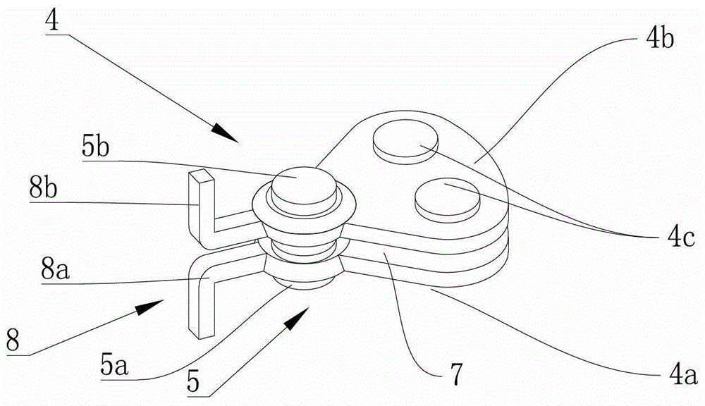
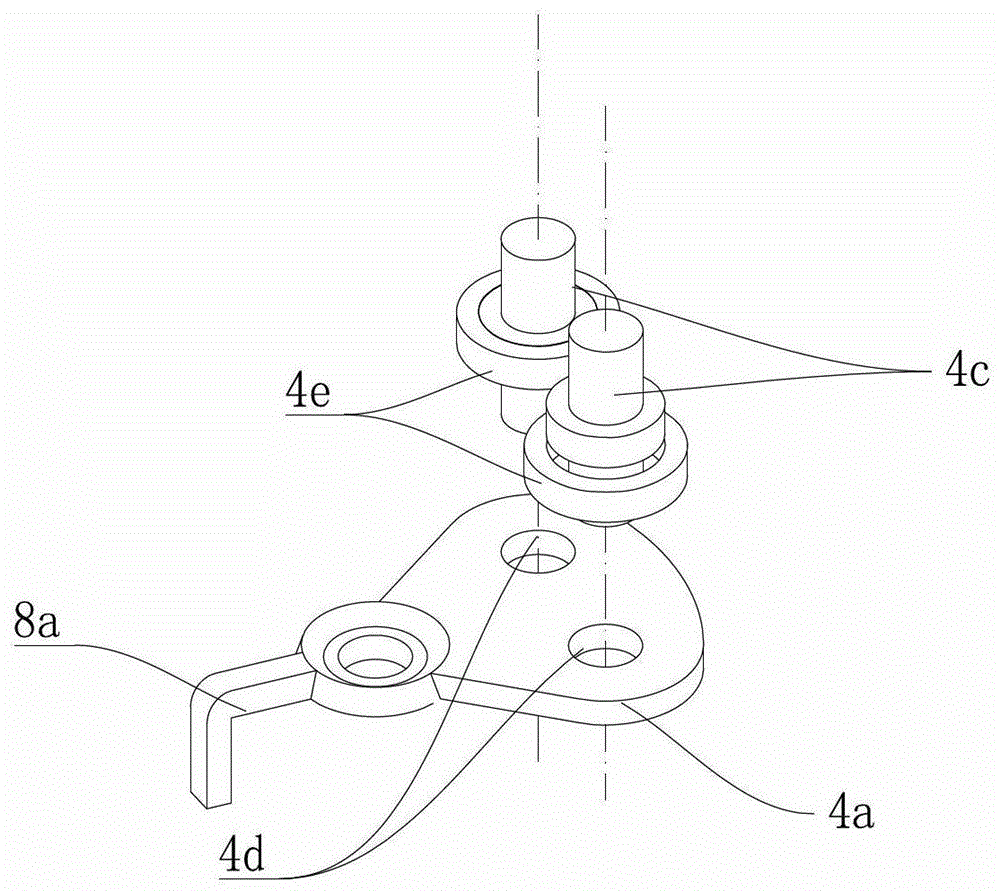
[0046] figure 1 It shows an embodiment of the double unlocking head control mechanism of the present invention, including a lock head assembly 11 and a lock-in lock assembly driven by the indoor lock core shaft 1c or the outdoor lock core shaft 1d to drive the lock tongue plate 2 to move along the lock-in and lock-out direction. Lock out mechanism. Wherein the lock head assembly 1 has an indoor lock head 1a and an outdoor lock head 1b, the indoor lock core shaft 1c of th...


PUM


Abstract

The invention discloses a control mechanism of a dual-opening lock. The control mechanism comprises a lock assembly, a lock-in and lock-out mechanism, a swinging piece and two switching pieces, wherein the lock-in and lock-out mechanism comprises an installing shaft, the installing shaft is located between lock cores of an indoor lock and an outdoor lock, the position of the installing shaft is fixed relative to lock core shafts, and the installing shaft is independent of the lock core shafts; the swinging piece is rotationally arranged on the installing shaft and is provided with sliding pins which are used for pushing a bolt plate to move along the lock-in and lock-out direction; the two switching pieces are used for respectively driving the swinging piece to rotate around the installing shaft under the driving of the corresponding lock core shafts; one switching piece does not rotate synchronously when the swinging piece is driven to rotate by the other switching piece; a gap which is used for a bolt plate to move along the lock-in and lock-out direction is reserved between the lock core of the indoor lock and the lock core of the outdoor lock.

Description

technical field [0001] The invention relates to the technical field of locks, in particular to a double-opening lock head control mechanism. Background technique [0002] The lock generally includes a lock head, a door lock bolt plate that is controlled by the lock head to protrude or retract in the direction of locking in and out, and a locking mechanism for the door lock bolt plate. In order to simplify the lock structure and reduce production costs, the applicant previously submitted a Chinese patent application document, the application number is 2012104412406, a door lock locking device, including a deadbolt plate, which can move linearly back and forth along the lock in and out direction. It is arranged in the lock case and is subject to the lock-out bias force pushed out along the lock-out direction; the bolt plate is formed with a traction groove; the pendulum is driven by a power shaft rotatably arranged on the lock case, and can It is reciprocally arranged in the ...

Claims


Application Information

Patent Timeline
Patent Type & Authority Patents(China)
IPC IPC(8): E05B63/00E05B15/00
Inventor 王斌坚
Owner WONLY SECURITY & PROTECTION TECH CO LTD
Learn More