Ultrasonic diagnosis equipment and ultrasonic diagnosis method supporting multi-probe synchronous scanning

A technology of ultrasonic diagnosis and equipment, which is applied in the direction of ultrasonic/sonic/infrasonic equipment control, ultrasonic/sonic/infrasonic diagnosis, sound wave diagnosis, etc. problems, to achieve the effect of avoiding the risk of sound power and accurate ultrasound images

Inactive Publication Date: 2014-10-22
SHENZHEN MINDRAY BIO MEDICAL ELECTRONICS CO LTD
View PDF5 Cites 13 Cited by
  • Summary
  • Abstract
  • Description
  • Claims
  • Application Information

AI Technical Summary

Problems solved by technology

However, this ultrasonic diagnostic equipment can only connect multiple probes to the system at the same time, and does not support simultaneous work and synchronous scanning of multiple probes, which cannot meet the needs of doctors for simultaneous diagnosis of different parts of the human body.

Method used


Image

  • Ultrasonic diagnosis equipment and ultrasonic diagnosis method supporting multi-probe synchronous scanning
  • Ultrasonic diagnosis equipment and ultrasonic diagnosis method supporting multi-probe synchronous scanning
  • Ultrasonic diagnosis equipment and ultrasonic diagnosis method supporting multi-probe synchronous scanning

Examples


Embodiment 2

[0085] The second embodiment includes the following steps:

[0086] Step 200: Control the multiple probes to switch within the scan pulse repetition time interval through the multiple probe high-voltage switches, and alternately scan different parts of the body surface of the diagnosed person with a predetermined scan time sequence.

[0087] Step 201, using the plurality of probes to scan different parts of the body surface of the person being diagnosed synchronously and in real time to obtain echo signals and transmit them to the imaging system;

[0088] Step 202, converting multiple echo signals sent back by the multiple probes into multiple ultrasonic images through the imaging system;

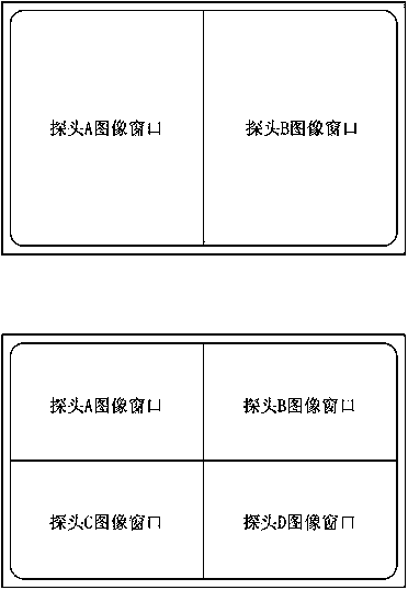
[0089] Step 203, receiving and synchronously displaying multiple processed ultrasound images output by the imaging system through the display module.

[0090] Wherein, the predetermined scanning sequence in step 200 is: the plurality of probes alternately scan different parts of the body s...

Embodiment 3

[0092] The present embodiment three comprises the following steps:

[0093] Step 300: Control the multiple probes to switch within the scan pulse repetition time interval through the multiple probe high-voltage switches, and alternately scan different parts of the body surface of the diagnosed person with a predetermined scan time sequence.

[0094] Step 301 , control each array element of the probe where it is located to alternately scan the body surface site corresponding to the probe through the array element high voltage switch set in the probe.

[0095] In a specific implementation, the switching of the high-voltage switch of the probe and the high-voltage switch of the array element is controlled by a control circuit.

[0096] Step 302, using the plurality of probes to scan different parts of the body surface of the diagnosed person synchronously and in real time, obtain echo signals and transmit them to the imaging system;

[0097] Step 303, converting multiple echo si...


PUM


Abstract

An ultrasonic diagnosis device and method that support synchronous scanning by multiple probes. The ultrasonic diagnosis device comprises a display module (1), an imaging system (3), and multiple probes (A, B, C, D). The multiple probes (A, B, C, D) closely contact different portions of the body surface of a diagnosed person, synchronously scan the different portions of the body surface of the diagnosed person in real time, obtain echo signals after the scanning, and then transmit the echo signals to the imaging system (3); the imaging system (3) converts the multiple echo signals transmitted by the multiple probes (A, B, C, D) into multiple ultrasonic images; and the display module (1) is coupled to the imaging system (3), receives the multiple ultrasonic images output by the imaging system (3) after processing, and synchronously displays the images. The multiple probes (A, B, C, D) work independently at the same time, so that the ultrasonic diagnosis device obtains image scanning data of the different probes at the same time, thereby meeting the requirement on diagnosing different body portions at the same time.

Description

technical field [0001] The invention relates to the field of medical equipment, in particular to an ultrasonic diagnostic equipment and method supporting multi-probe synchronous scanning. Background technique [0002] Probes are important components in ultrasonic diagnostic equipment. It is responsible for converting the electrical signal into an acoustic signal and transmitting it into the human body; then converting the acoustic signal reflected by the human tissue into an electrical signal, which is transmitted to the signal processing link in the ultrasonic diagnostic equipment for imaging. [0003] With the development of modern science and technology, ultrasonic diagnostic technology is becoming more and more perfect. Ultrasonic diagnostic equipment is widely used in the clinical field, and various probes with different operating frequencies and shapes are also put into clinical applications. [0004] According to the depth, shape and structure of different diagnosti...

Claims


Application Information

Patent Timeline
Patent Type & Authority Applications(China)
IPC IPC(8): A61B8/00
CPCA61B8/145A61B8/42A61B8/4227A61B8/4236A61B8/4416A61B8/4477A61B8/4488A61B8/463A61B8/483A61B8/485A61B8/5207A61B8/54G01S7/52085G01S15/8909A61B8/4483
Inventor 刘硕李勇
Owner SHENZHEN MINDRAY BIO MEDICAL ELECTRONICS CO LTD
Why Eureka
Try Eureka