Monitoring equipment with ultrasonic scanning monitoring function, ultrasonic device and corresponding method

A technology of ultrasonic scanning and monitoring equipment, applied in ultrasonic/sonic/infrasonic diagnosis, application, sonic diagnosis and other directions, can solve the problems of patient discomfort, inability to use long-term monitoring, and difficulty in meeting wider clinical needs, etc. Accurate ultrasound images, avoid sound power risks, and meet clinical needs

Inactive Publication Date: 2014-09-24
SHENZHEN MINDRAY BIO MEDICAL ELECTRONICS CO LTD +1
View PDF6 Cites 15 Cited by
  • Summary
  • Abstract
  • Description
  • Claims
  • Application Information

AI Technical Summary

Problems solved by technology

[0004] The traditional ultrasonic diagnostic system is only installed in the ultrasound department, which requires the doctor to hold the ultrasonic probe to scan the patient's examination site to obtain ultrasonic images for short-term diagnosis
For some of the above-mentioned clinical situations that require long-term monitoring of various physiological parameters of patients (including real-time information of organs and tissues, such as hemodynamic parameters), the existing ultrasonic diagnostic system cannot be applied to such long-term monitoring. In time monitoring, it is difficult to meet the broader clinical needs
In addition, in the prior art, for ultrasonic scanning of cardiac hemodynamics, the probe is often placed in the patient's esophagus. If a transesophageal probe is used to monitor the patient for a long time, it will bring great harm to the patient. discomfort

Method used


Image

  • Monitoring equipment with ultrasonic scanning monitoring function, ultrasonic device and corresponding method
  • Monitoring equipment with ultrasonic scanning monitoring function, ultrasonic device and corresponding method
  • Monitoring equipment with ultrasonic scanning monitoring function, ultrasonic device and corresponding method

Examples


Embodiment Construction

[0062] The following will clearly and completely describe the technical solutions in the embodiments of the present invention with reference to the accompanying drawings in the embodiments of the present invention. Obviously, the described embodiments are only some, not all, embodiments of the present invention. Based on the embodiments of the present invention, all other embodiments obtained by persons of ordinary skill in the art without creative efforts fall within the protection scope of the present invention.

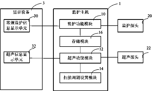
[0063] Such as figure 1 As shown, it is a schematic structural diagram of an embodiment of a monitoring device with an ultrasonic scanning monitoring function in the present invention; the monitoring device with an ultrasonic scanning monitoring function includes a monitoring host that includes a monitoring function module 10 and an ultrasonic function module 12 1. Monitoring probe 20, ultrasonic probe 22 and display device 3, wherein:

[0064] The monitoring func...


PUM


Abstract

A monitoring and nursing device with ultrasonic scanning and monitoring functions comprises a monitoring and nursing function module (10), a monitoring and nursing detector (20), an ultrasonic function module (12), an ultrasonic detector (22), and a display device (3). The monitoring and nursing function module (10) is used for mentoring a routine physiological parameter. The ultrasonic function module (12) is used for monitoring a detected person by using ultrasonic scanning, and obtaining a corresponding ultrasonic image and a physiological parameter of the detected person. The monitoring and nursing detector (20) is coupled to the monitoring and nursing function module (10). The ultrasonic detector (22) is coupled to the ultrasonic function module (12). The display device (3) is coupled to the monitoring and nursing function module (10) and the ultrasonic function module (12), and receives and displays a physiological parameter of routine monitoring and nursing as well as the ultrasonic image and the physiological parameter of the detected person. Also disclosed are a monitoring and nursing method implemented on the monitoring and nursing device, and an ultrasonic apparatus for monitoring and nursing. By means of the device and the method, a physiological parameter of routine monitoring and nursing can be monitored, ultrasonic scanning can be performed according to a preset time period and duration to obtain and display an ultrasonic image and a physiological parameter, thereby better meeting clinical requirements.

Description

technical field [0001] The invention relates to the field of medical equipment, in particular to a monitoring device with an ultrasonic scanning monitoring function, an ultrasonic device and a corresponding method Background technique [0002] In the diagnosis and clinical monitoring of critically ill patients, monitors that can monitor the vital signs of patients are often used. The heart monitoring information provided by existing monitors includes parameters such as electrocardiographic monitoring (ECG or EKG), blood pressure, and blood oxygen saturation (SPO2). Among them, EKG parameters are easily disturbed. For example, poor electrode contact and improper human operation may cause ECG measurement parameters to deviate from the actual situation. The resulting false alarms will lead to alarm fatigue and affect the timeliness of doctors to deal with emergencies. On the other hand, the blood pressure parameters generally appear on the display interface of the monitor as n...

Claims


Application Information

Patent Timeline
Patent Type & Authority Applications(China)
IPC IPC(8): A61B8/00
CPCA61B8/00A61B5/00A61B8/461A61B8/5223A61B8/463A61B8/14A61B8/483A61B8/485A61B8/486A61B8/488G16H50/30
Inventor 李勇刘硕刘进宋海波
Owner SHENZHEN MINDRAY BIO MEDICAL ELECTRONICS CO LTD
Why Eureka
Try Eureka